Flowmeter
a flowmeter and flow rate technology, applied in the field of flowmeters, can solve the problems of erosive media damage to the inner surface of the connection area, particularly high load on the connection area, etc., and achieve the effect of being particularly flexible in design
- Summary
- Abstract
- Description
- Claims
- Application Information
AI Technical Summary
Benefits of technology
Problems solved by technology
Method used
Image
Examples
first embodiment
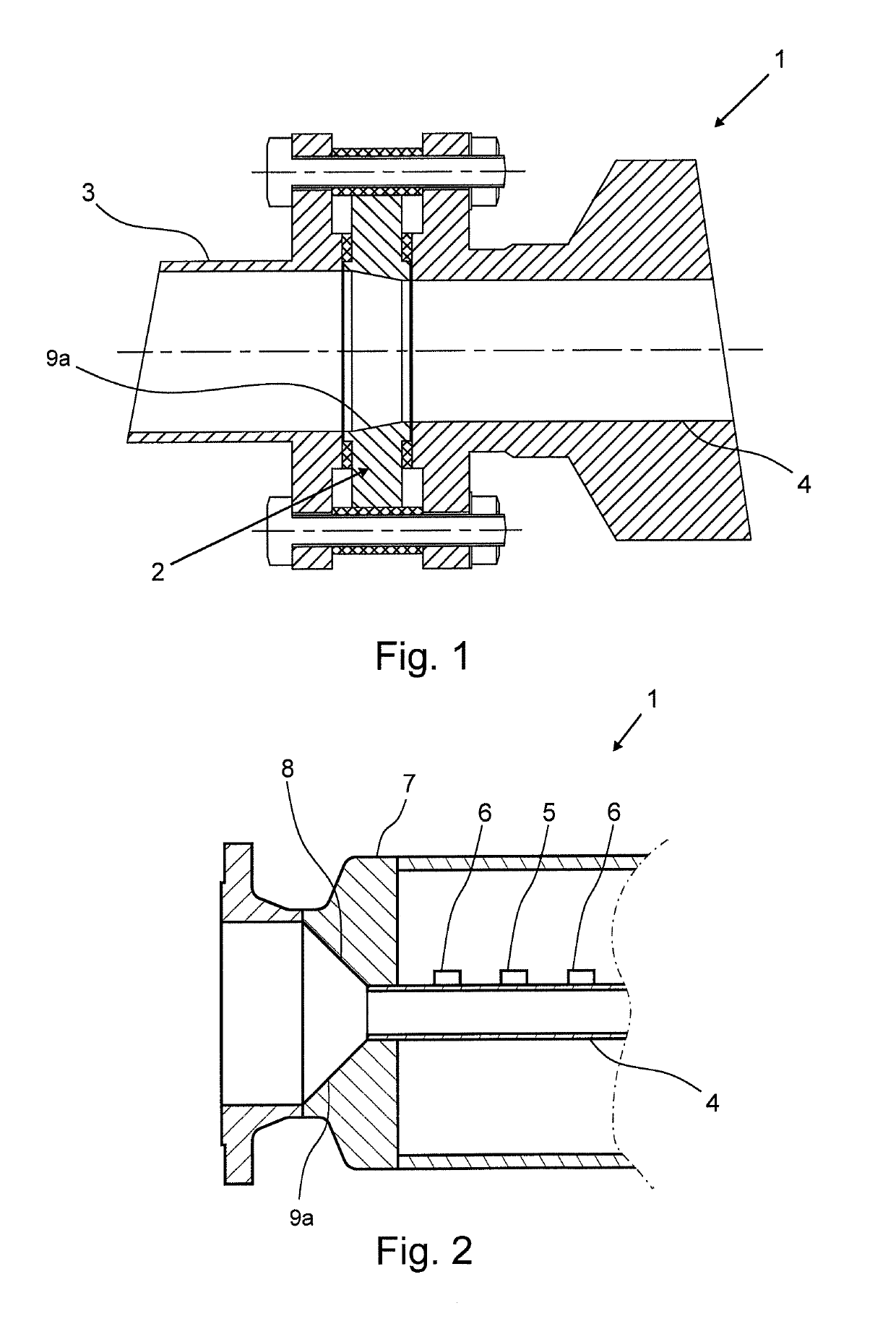
[0030]FIG. 2 shows The flowmeter 1 according to the invention, wherein the flowmeter is designed as a Coriolis mass flowmeter having a measuring tube 4, an oscillation generator 5 and two oscillation sensors 6 for recording the oscillation of the measuring tube 4 during operation. Additionally, an inlet element 7 is provided that is connected to the measuring tube 4 by means of a welding connection. Furthermore, an inflow element 8 is provided that is arranged within the inlet element 7 and that is detachably connected to the inlet element 7. In the shown embodiment, the inflow element 8 is designed as a simple flow cross section reducer 9a for reducing the cross section to the cross section of the measuring tube 4. Due to the detachable connection, the inflow element 8 can be particularly easily replaced when it is damaged or worn. As opposed to the design of the prior art illustrated in FIG. 1, the measurement setup shown in FIG. 2 has the advantage that the replaceable inflow ele...
second embodiment
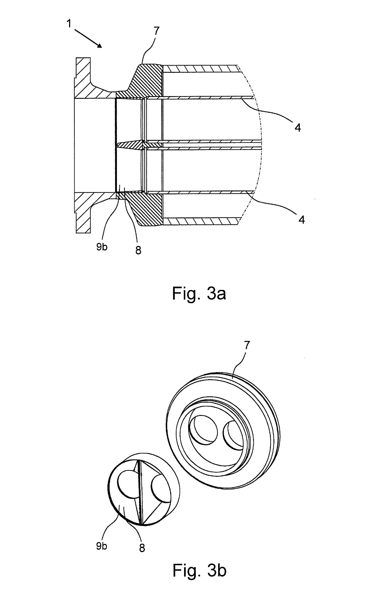
[0031]FIG. 3a shows the end section of the flowmeter 1 that is designed as a Coriolis mass flowmeter 1. The Coriolis mass flowmeter 1 has two measuring tubes 4, an inlet element 7 that is connected to the measuring tubes 4 and a flow splitter 9b that is arranged within the inlet element 7 before the measuring tubes 4. The flow splitter 9b is simultaneously designed as inflow element 8 that is detachably connected to the inlet element 7. FIG. 3b shows the combination of the inlet element 7 and the flow splitter 9b designed as inflow element 8 in an exploded view. This design has the advantage that the replaceable inflow element 8 is integrated in the setup of the Coriolis mass flowmeter 1.
third embodiment
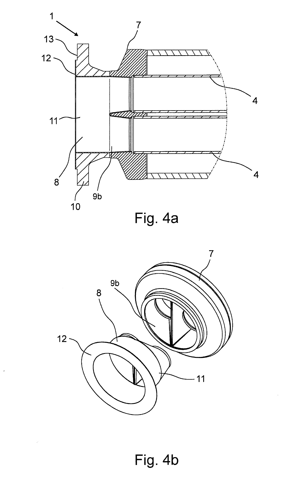
[0032]FIG. 4a shows a sectional view of the end sections of the flowmeter 1 that is designed as Coriolis mass flowmeter 1. The illustrated Coriolis mass flowmeter 1 has two measuring tubes 4, an inlet element 7 that is connected to the measuring tubes 4 and a flow splitter 9b. A flange element 10 is connected to the inlet element 7 for connection to external piping 3. Additionally, an inflow element 8 designed as protective shield 11 is provided that covers both the flow splitter 9b as well as the flange element 10. Additionally, the inflow element 8 also has a protective shield flange 12, which rests on the connecting area 13 of the flange element 10. FIG. 4b shows the combination of the inlet element 7 with the flow splitter 9b and the inflow element 8 designed as protective shield 11 in an exploded view.
PUM
 Abstract
Description
Claims
Application Information
 - R&D
- Intellectual Property
- Life Sciences
- Materials
- Tech Scout
- Unparalleled Data Quality
- Higher Quality Content
- 60% Fewer Hallucinations
Browse by: Latest US Patents, China's latest patents, Technical Efficacy Thesaurus, Application Domain, Technology Topic, Popular Technical Reports.
© 2025 PatSnap. All rights reserved.Legal|Privacy policy|Modern Slavery Act Transparency Statement|Sitemap|About US| Contact US: help@patsnap.com


