Cartridge bearing assembly for roller conveyors

a technology of roller conveyors and bearings, which is applied in the direction of bearings, shafts and bearings, rolling contact bearings, etc., can solve the problems of significant maintenance efforts and manufacturing costs, complex assembly, and complex construction of rollers used in this type of conveyors. , to achieve the effect of facilitating assembly, minimizing manufacturing costs, and minimizing wear and maintenan

Active Publication Date: 2019-11-12
LEWCO
View PDF19 Cites 0 Cited by
  • Summary
  • Abstract
  • Description
  • Claims
  • Application Information

AI Technical Summary

Benefits of technology

[0008]In accordance and attuned with the present invention, a cartridge bearing assembly for a conveyor roller configured for use with torque transmitting devices that minimizes wear and maintenance, facilitates ease of assembly, and minimizes manufacturing costs and complexity of the conveyor rollers has surprisingly been discovered.

Problems solved by technology

Since the singulator conveyor system requires the series of the drive belts, consequently, there are also a large number of moving parts resulting in significant maintenance efforts and manufacturing costs.
However, the typical construction of the rollers used in this type of conveyor is complex due to a high duty cycle and a requirement for minimal maintenance of the conveyor rollers.
The spring loading causes the shaft assembly to urge a shaft outwardly from ends of the rollers as the shaft and / or conveyor frame begins to wear.
However, as mentioned above, these assemblies are complex and can be costly to manufacture and are unable to withstand heavier loads and higher speeds or loads applied to the rollers.
Additionally, rollers disposed perpendicular to the frame also include complex assemblies similar to the disposed at an angle.
However, these examples of spring loaded rollers are also complex, costly to manufacture and maintain, difficult to assemble, and also may not be able to withstand higher speeds or heavier loads of rollers.

Method used


Image

  • Cartridge bearing assembly for roller conveyors
  • Cartridge bearing assembly for roller conveyors
  • Cartridge bearing assembly for roller conveyors

Examples


Embodiment Construction

[0019]The following detailed description and appended drawings describe and illustrate various embodiments of the invention. The description and drawings serve to enable one skilled in the art to make and use the invention, and are not intended to limit the scope of the invention in any manner. In respect of the methods disclosed, the steps presented are exemplary in nature, and thus, the order of the steps is not necessary or critical. As used herein, substantially is defined at “to a considerable degree” or “proximate” or as otherwise understood by one ordinarily skilled in the art.

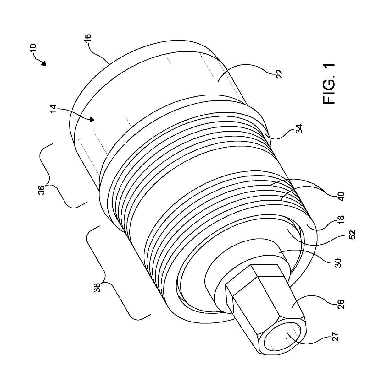
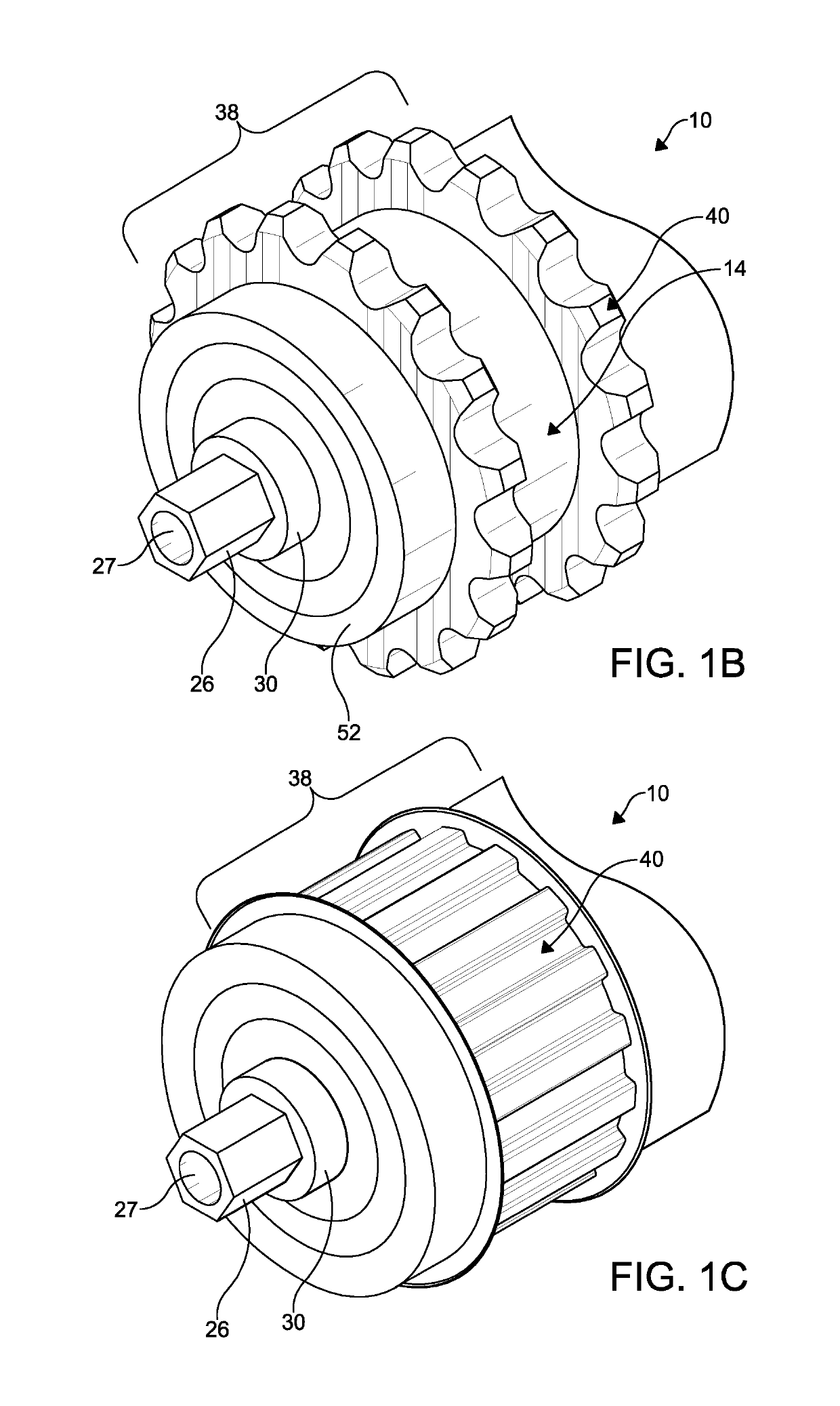
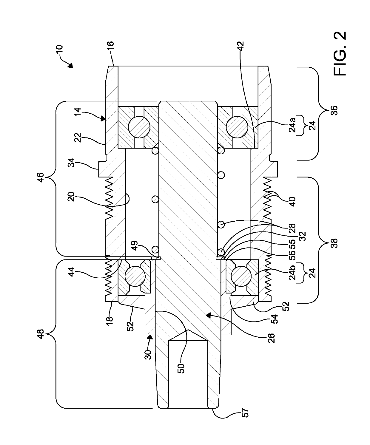
[0020]FIGS. 1A-4 illustrate a cartridge bearing assembly 10 configured for coupling to an end of a roller 12 employed in a roller conveyor system (not shown) according to an embodiment of the disclosure. The cartridge bearing assembly 10 is particularly advantageous for a roller employed in a singulation type roller conveyor system. As described herein, a singulation type roller conveyor system refers t...


PUM


Abstract

A cartridge bearing assembly for a roller conveyor system includes a housing having a first end, a second end opposing the first end, an inner surface, and an outer surface. A pair of bearings is spaced from each other and disposed in the housing. An shaft is received by the pair of bearings. The shaft is formed from a plastic material. A spring is disposed about a first portion of the shaft intermediate the pair of bearings. The spring biases the shaft outwardly from the first end of the housing.

Description

CROSS-REFERENCE TO RELATED APPLICATIONS[0001]This application claims the benefit of U.S. Provisional Patent Application Ser. No. 62 / 469,124, filed on Mar. 9, 2017. The entire disclosure of the above patent application is hereby incorporated herein by reference.FIELD OF INVENTION[0002]The invention relates to conveyor rollers and more particularly to a cartridge bearing assembly for conveyor rollers.BACKGROUND[0003]Commonly, a singulator conveyor system is used for alignment and singulation of packages, goods, and materials. An example of a singulator conveyor system is disclosed in U.S. Pat. No. 5,769,204, hereby incorporated herein by reference in its entirety. For example, the singulator conveyor system is employed in packaging facilities such as courier facilities so packaging can be identified and automatically processed through sorting equipment. The singulator conveyor system has skewed or angled rollers to move the packages to one side of the singulator conveyor system, typic...

Claims


Application Information

Patent Timeline
Patent Type & Authority Patents(United States)
IPC IPC(8): B65G39/09B65G39/02F16C13/02F16C19/54B65G39/12
CPCB65G39/09F16C13/022B65G39/025F16C2326/58B65G39/12B65G2207/48F16C19/54
Inventor GUERRA, GERALD T.SPARLING, ALBERT E.FRESCH, CHARLES J.
Owner LEWCO
Why Eureka
Try Eureka