
Device for fractional laser-based-treatment

a fractional laser and treatment device technology, applied in the field of treatment devices for fractional laser-based skin treatment, can solve the problems of significant reduction of the freedom with which a user can operate the treatment device, overlap of lesions, etc., and achieve the effect of improving the degree of freedom

Active Publication Date: 2019-10-29
KONINKLJIJKE PHILIPS NV
View PDF12 Cites 0 Cited by
  • Summary
  • Abstract
  • Description
  • Claims
  • Application Information

AI Technical Summary

Benefits of technology

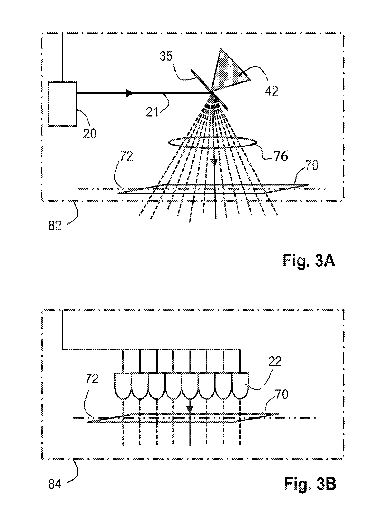
The treatment device described in this patent is designed to apply fractional laser-based skin treatment safely by preventing too much damage inside the skin tissue caused by overlapping lesions. This is especially important for consumers who are typically non-medical and only marginally trained. The device uses a treatment laser emitting laser light from a plurality of predefined locations covering an elongated area of an emission window extending along the treatment axis. This elongated area allows the device to treat a skin area when moved relative to the skin surface. The device also includes a motion sensor sensing the motion of the device relative to the skin surface and a controller activating the treatment laser to generate a non-zero sequence of at least one of the predefined locations when the sensed motion has a component in a direction parallel to the treatment axis. This results in improved freedom of use of the device. In an embodiment, the treatment device comprises an array of treatment lasers, each laser emitting laser light towards one of the predefined locations. This simplifies the optical complexity of the treatment device.

Problems solved by technology

With such known apparatus, overlap of lesions may occur when the motion of the treatment device relative to the skin surface is not done correctly by the user.
Although this safety measure is important, it also significantly reduces the freedom with which a user can operate the treatment device.

Method used


Image

  • Device for fractional laser-based-treatment
  • Device for fractional laser-based-treatment
  • Device for fractional laser-based-treatment

Examples


Embodiment Construction

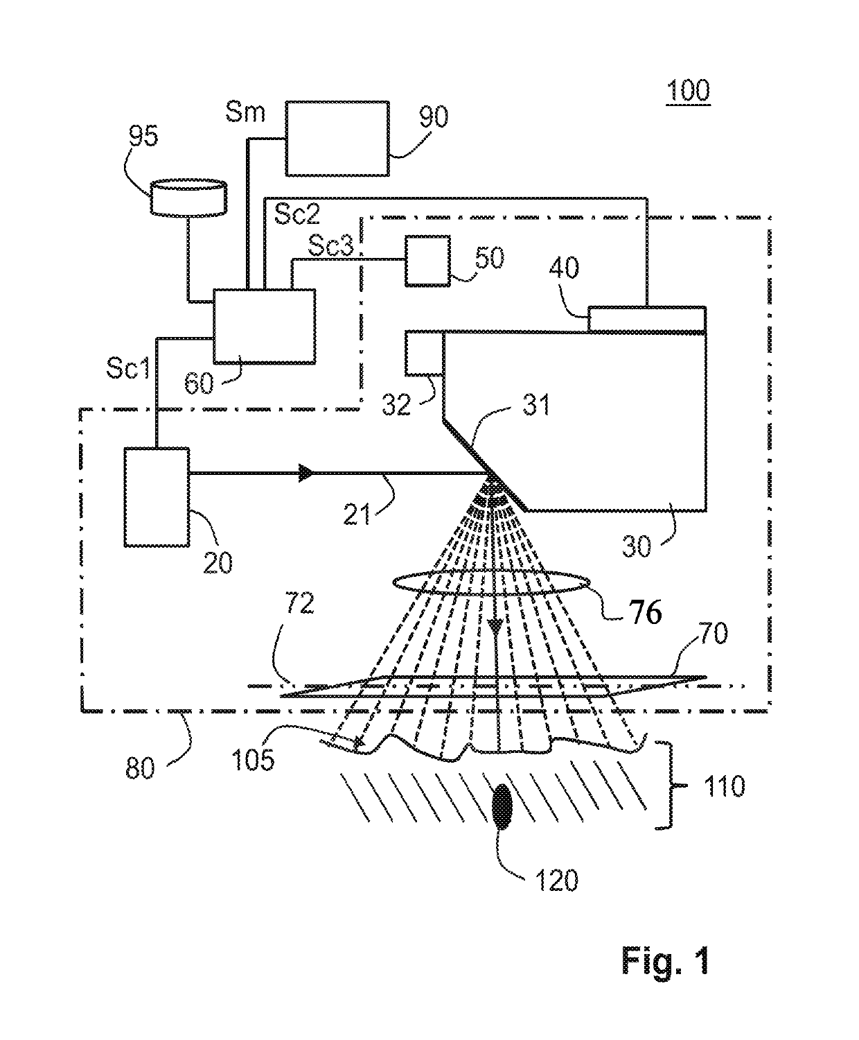
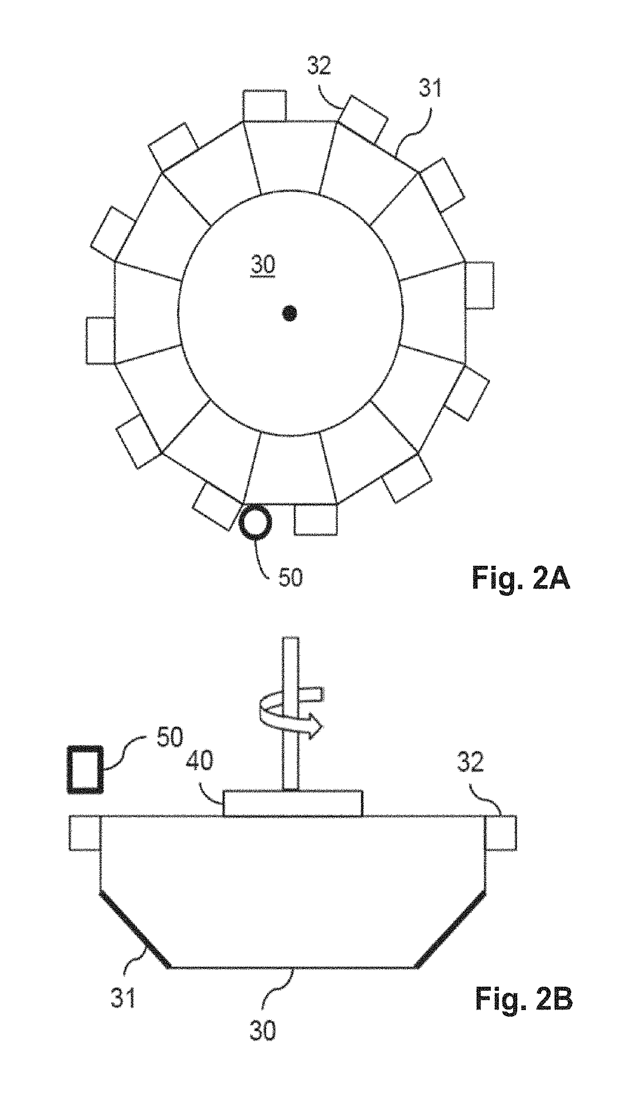
[0039]FIG. 1 schematically shows a treatment device 100 according to the invention. The treatment device 100 comprises a treatment laser 20 for providing a light beam 21 and a deflection wheel 30 with a plurality of deflection elements 31 which deflect the light beam 21 through an objective lens 76 and an emission window 70 of the treatment device 100 towards a skin tissue 110. Each deflection element 31 provides a respective different direction of reflection for the light beam 21, causing the reflected light beam 21 to be emitted from the treatment device 100 via different predefined locations 74 in the emission window 70 (see FIG. 4). Accordingly, during rotation of the deflection wheel 30, the treatment device 100 generates a non-zero sequence of at least one of the plurality of predefined locations 74 in the emission window 70 from which the light beam 21 is consecutively reflected towards a corresponding plurality of different positions at the skin surface 105. At the skin surf...


PUM


Abstract

A treatment device for fractional laser-based skin treatment includes an emission window having an elongated area and predefined locations that are arranged in an elongated array which extends along a treatment axis of the window. A treatment generator has a treatment laser for emitting laser light towards skin tissue from the predefined locations in the emission window for generating, in use, laser-based lesions inside the skin tissue. The treatment device also includes a motion sensor for sensing motion of the treatment device relative to the skin surface, and a controller for determining a non-zero sequence of at least one of the predefined locations from which laser light is consecutively emitted in dependence on the sensed motion. The controller allows generation of the non-zero sequence when the sensed motion of the treatment device relative to the skin surface only has a component in a direction parallel to the treatment axis.

Description

[0001]This application is the U.S. National Phase application under 35 U.S.C. § 371 of International Application No. PCT / EP2014 / 066325, filed on Jul. 30, 2014, which claims the benefit of International Application No. 13178527.1 filed on Jul. 30, 2013. These applications are hereby incorporated by reference herein.FIELD OF THE INVENTION[0002]This invention relates to a treatment device for fractional laser-based skin treatment.BACKGROUND OF THE INVENTION[0003]The desire to maintain a youthful appearance by reducing wrinkles and fine lines in the skin is an important issue in human society. Many techniques have been designed to achieve the above issue, one of which is skin rejuvenation using, for example, fractional photo-thermolysis. This fractional photo-thermolysis may, for example, be used for treatment of fine lines, wrinkles, unevenness of pigmentation and dyschromia. Fractional photo-thermolysis is based on creating micro-zones of damage inside skin tissue within areas or volu...

Claims


Application Information

Patent Timeline
Patent Type & Authority Patents(United States)
IPC IPC(8): A61B5/06A61B18/20A61B17/00A61B18/00
CPCA61B18/203A61B2017/00075A61B2018/00636A61B2018/0047A61B2018/00642A61B2018/00702A61B2018/00684A61B2018/205547A61B2018/208A61B2018/20351A61B2018/20359A61B2018/00672A61B2018/00452
Inventor CHLON, CAECILIA HENDRINA THEODORAJURNA, MARTINNUIJS, ANTONIUS MAARTENGROOTEL-RENSEN, MARIA ANGELINA JOSEPHAMOESKOPS, BASTIAAN WILHELMUS MARIA
Owner KONINKLJIJKE PHILIPS NV
Learn More