
Imaging device

a technology of a device and an image, applied in the field of image devices, can solve the problems of increasing the cost of the entire device, and achieve the effects of controlling the power consumption, controlling the cost increase, and controlling the freedom of layou

Inactive Publication Date: 2013-02-05
RICOH KK
View PDF10 Cites 0 Cited by
  • Summary
  • Abstract
  • Description
  • Claims
  • Application Information

AI Technical Summary

Benefits of technology

The purpose of this patent is to create an imaging device that can manage how it corrects for camera shake and other image quality issues. The goal is to make it more efficient and cost-effective, while also controlling power consumption.

Problems solved by technology

However, since the stage is movably provided in the one end of the fixing cylinder, if the positional control (hereinafter, electrical holding) of the stage using the magnetic force of the permanent magnet and the coil is stopped, the stage moves in the movable range, and crushing or impact with the end portion of the movable range may be caused.
For this reason, the degree of freedom of the layout of the camera shake correction function and the like is decreased and also the entire costs are increased.

Method used


Image

  • Imaging device
  • Imaging device
  • Imaging device

Examples


embodiment

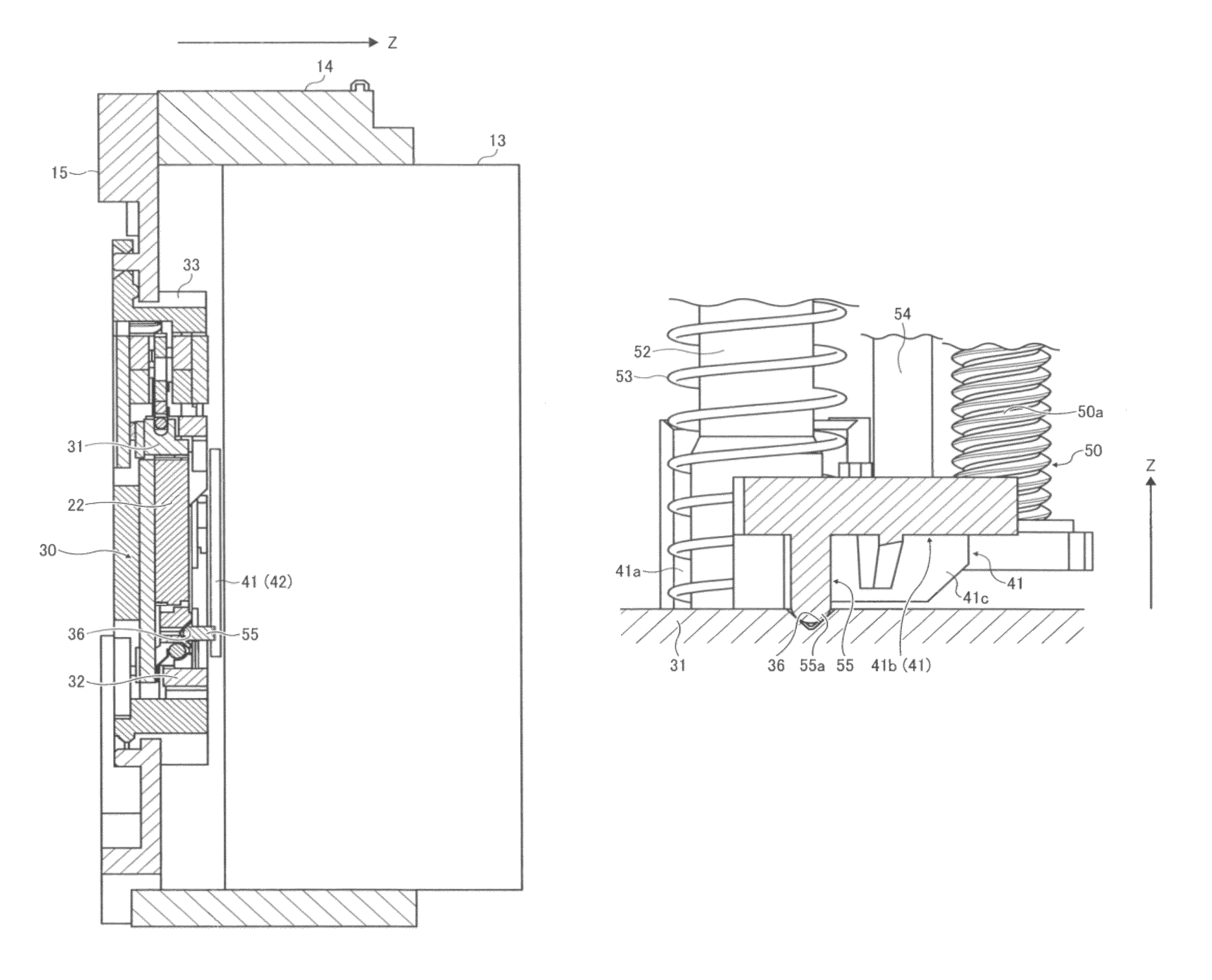
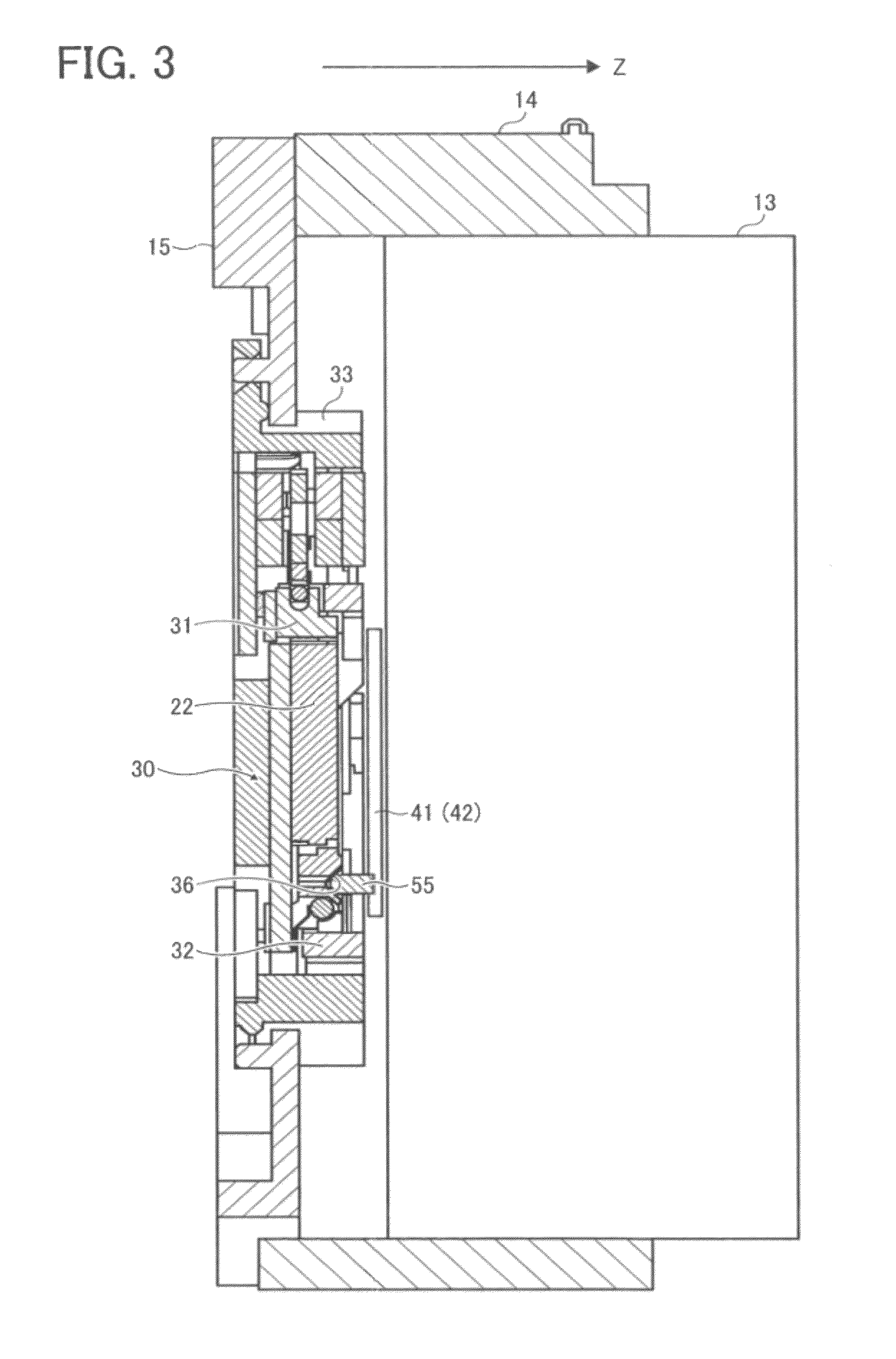
[0025]As one example of an imaging device according to one embodiment of the present invention, a digital camera 10 will be described with reference to FIGS. 1-10. FIG. 8A provides a partially enlarged view illustrating a state in which an engagement projection 55 engages with an engagement hole 36 in a housed state in FIG. 3. FIG. 8B provides a partially enlarged view illustrating a state in which the engagement projection 55 disengages from the engagement hole 36 in a shooting standby state in FIG. 4.

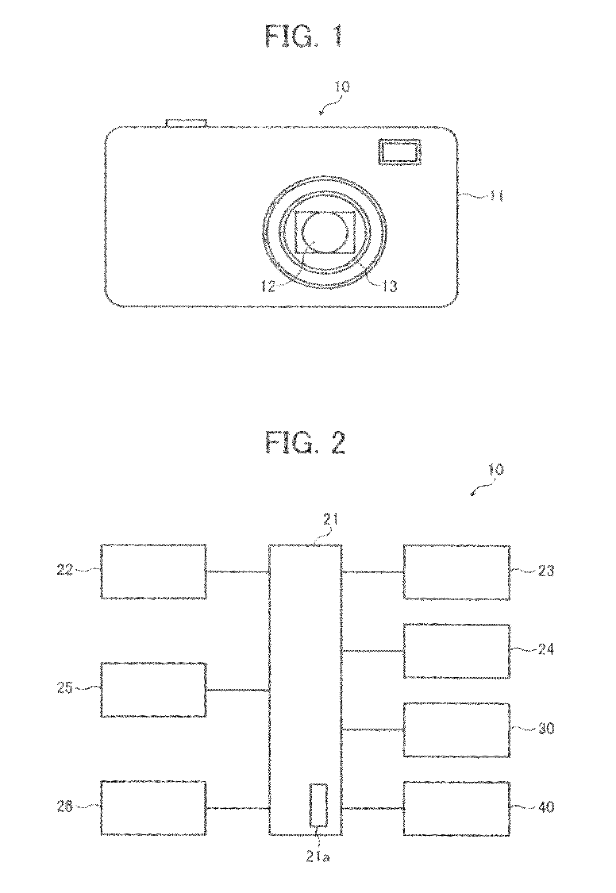
[0026]The digital camera 10 of the present embodiment includes a camera shake correction function which corrects camera shake by moving an imaging element in a plane vertical to the optical axis direction. As illustrated in FIG. 1, the digital camera 10 includes a lens barrel 13 having a part of a shooting optical system 12 on the front face side of a camera body 11. This shooting optical system 12 includes a focus lens 42 (refer to FIGS. 5, 7), a fixing lens, a zoom lens, a shutter u...


PUM


Abstract

An imaging device having a housed state in which a plurality of optical members of an imaging optical system is housed and a shooting standby state in which at least a part of the optical members is moved on a subject side includes a stage configured to be movable along a plane orthogonal to an optical axis so as to move an imaging element which obtains a subject image by the shooting optical system in the plane, a plurality of optical member holding frames each of which is configured to hold each of the optical members and a lens holding frame driver configured to drive each of the optical member holding frames, the stage includes an engagement hole facing to the shooting optical system, and one of the optical member holding frames includes an engagement projection which is engageable with the engagement hole.

Description

PRIORITY CLAIM[0001]The present application is based on and claims priority from Japanese Patent Application No. 2010-017029, filed on Jan. 28, 2010, the disclosure of which is hereby incorporated by reference in its entirety.BACKGROUND OF THE INVENTION[0002]1. Field of the Invention[0003]The present invention relates to an imaging device such as a digital still camera and a digital video camera (hereinafter, a digital camera) each having a function which corrects camera shake in shooting.[0004]2. Description of the Related Art[0005]As an imaging device in which a subject image is received on an imaging element (for example, a CCD) via a shooting lens system (shooting optical system), and a digital image corresponding to the subject image is produced based on image signals from the imaging element, a digital camera having a function which corrects camera shake in shooting, a so-called camera shake correction function, has recently been developed for practical use.[0006]As such a cam...

Claims


Application Information

Patent Timeline
Patent Type & Authority Patents(United States)
IPC IPC(8): H04N5/225H04N5/228H04N23/40G03B5/00G03B7/00G03B17/02G03B17/04H04N101/00
CPCG03B5/02G03B17/02H04N5/2251H04N5/2252H04N5/23248H04N5/23287H04N23/51H04N23/55H04N23/651H04N23/68H04N23/687
Inventor ANDO, TAKASHI
Owner RICOH KK
Learn More