
Apparatus, method and system for providing enhanced mechanical protection for thin beams

a technology of thin beams and mechanical protection, applied in the direction of fluid speed measurement, optical elements, instruments, etc., can solve the problems of reducing the “free movement” of the micro-mechanical beam, and achieve the effect of limiting the “free movement” and enhancing protection

Inactive Publication Date: 2007-05-31
ROBERT BOSCH GMBH
View PDF13 Cites 0 Cited by
  • Summary
  • Abstract
  • Description
  • Claims
  • Application Information

AI Technical Summary

Benefits of technology

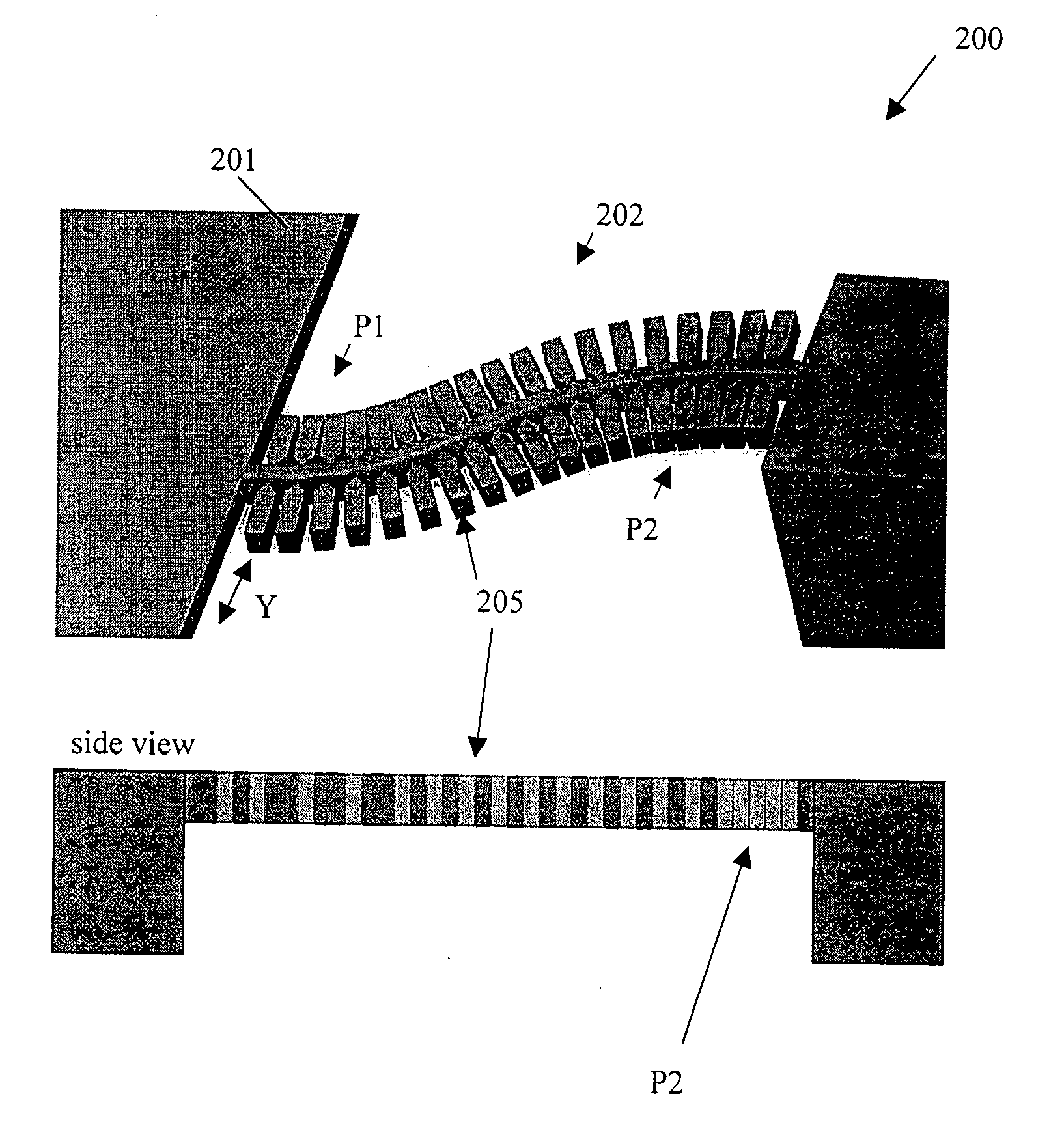
The present invention provides an improved way to protect micro-mechanical torsional beam springs by adding attachable support structures that limit bending actions at specific points along the beam. These support structures can increase bending stiffness without significantly influencing torsional stiffness. This makes the micro-mechanical beam more robust and able to withstand harsh environmental conditions. The support structures can also make the production of moveable structures and mirrors with higher yield and mass application feasibility. The invention can be used in various devices such as bar-code readers, leveling devices, scanners, display technology devices, and micro-mechanical mirrors.

Problems solved by technology

However, such changes to the length and thickness may decrease the “freedom of movement” of the micro-mechanical beam.

Method used


Image

  • Apparatus, method and system for providing enhanced mechanical protection for thin beams
  • Apparatus, method and system for providing enhanced mechanical protection for thin beams
  • Apparatus, method and system for providing enhanced mechanical protection for thin beams

Examples


Embodiment Construction

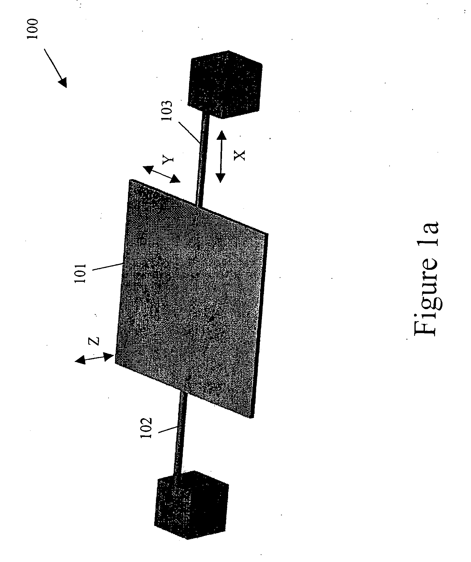
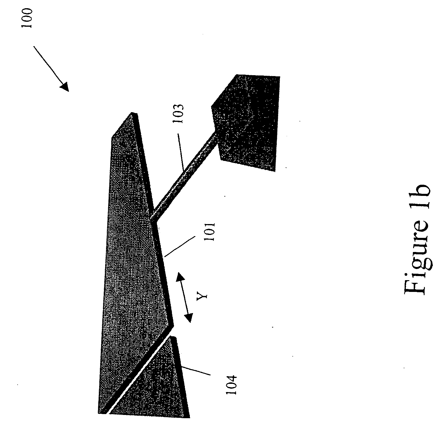
[0038]FIG. 1a shows a configuration of a micro-mechanical mirror arrangement 100. The micro-mechanical arrangement 100 includes a micro-mechanical mirror plate 101 suspended by two torsional micro-mechanical beams 102 and 103. The micro-mechanical beams 102, 103 permit a certain “freedom of movement” of the micro-mechanical mirror plate 101. In particular, the tension of the micro-mechanical beams 102, 103 restricts a movement of the micro-mechanical mirror plate 101 in a direction X along the axis of the micro-mechanical beams 102, 103, and at the same time permits movement in a direction Y that is in-plane with the micro-mechanical mirror plate 101 (that is, perpendicular to the axis of the micro-mechanical beams 102, 103 and a direction Z that is vertical to the plane of the micro-mechanical mirror plate 101).

[0039] To increase the freedom of movement of the micro-mechanical mirror plate 101, the micro-mechanical beams 102, 103 may be extended lengthwise in the direction X along...


PUM


Abstract

An arrangement for use with a micro-mechanical beam, in which a plurality of support structures are configured to directly attach to the micro-mechanical beam to increase bending stiffness of the micro-mechanical beam without significantly influencing torsional stiffness. At least two of the support structures are arranged to touch each upon reaching a predetermined bending action of the micro-mechanical beam and prevent a further bending action of the micro-mechanical beam, and at least two of the support structures are non-identical.

Description

FIELD OF THE INVENTION [0001] The present invention relates to an improved micro-mechanical beam or spring configuration for using micro-mechanical applications, micro-mechanical mirrors. BACKGROUND OF THE INVENTION [0002] German Published Patent Application No. 198 51 667 refers to a basic configuration of a micro-mechanical mirror arrangement, in which a micro-mechanical mirror plate is suspended by one or more torsional beams or beam springs. To allow large deflection angles of the mirror plate, the torsional beams may be required to be thin and long which may be prone to break. [0003] German Published Patent Application No. 199 63 382 and German Published Patent Application No. 199 41 045 refer to a modification which may provide a more robust configuration of the micro-mechanical mirror arrangement. The modification may relieve stress upon the micro-mechanical torsional beams if the micro-mechanical mirror plate is moved in a direction that is vertical to the plane of the micro...

Claims


Application Information

Patent Timeline
Patent Type & Authority Applications(United States)
IPC IPC(8): G02B7/182B81B3/00B81B7/00G02B26/10G02B26/08
CPCB81B3/007B81B2203/0109B81B2203/058G02B26/0833B81B2201/042B81B2203/0154
Inventor NIENDORF, ANDREASFREY, WILHELMPAN, ZHIYU
Owner ROBERT BOSCH GMBH
Learn More