
Hydromechanical pressure compensation control of a variable displacement pump in a centrifugal pumping and metering system and associated method

a technology of centrifugal pumping and metering system, applied in the field of pumping system, can solve the problems of limited pressure ripple, excessively large pump system, series of system problems, etc., and achieve the effects of reducing rotational speed, reducing viscous drag, and improving the inlet performance characteristics of centrifugal pumps

Active Publication Date: 2019-10-22
EATON INTELLIGENT POWER LTD
View PDF25 Cites 1 Cited by
  • Summary
  • Abstract
  • Description
  • Claims
  • Application Information

AI Technical Summary

Benefits of technology

The patent text describes a method for improving the performance of a centrifugal pump by using an inducer stage and a reduced rotational speed. This reduces viscous drag and allows for better inlet performance. Additionally, the use of a variable displacement ring pump and the free rotation of a cam ring are also recommended to further optimize pump performance.

Problems solved by technology

Further, the centrifugal pump is generally lightweight, is deemed to have an extended life, has limited pressure ripple, and is generally conducive for a wide array of downstream uses.
Engine start is one area because the high speed centrifugal pump does not provide the required elevated fuel pressures for start-up until the engine speed has increased to a certain level.
However, the pump system can become excessively large for the balance of pump operating conditions, i.e., idle, cruise, climb, etc. if engine start-up were the only parameter concern.
A large pump, in turn, creates a series of system issues revolving around the thermal impacts on the system.
Likewise, there are size constraints and weight issues that must be addressed in designing an effective fuel pump system.

Method used


Image

  • Hydromechanical pressure compensation control of a variable displacement pump in a centrifugal pumping and metering system and associated method
  • Hydromechanical pressure compensation control of a variable displacement pump in a centrifugal pumping and metering system and associated method
  • Hydromechanical pressure compensation control of a variable displacement pump in a centrifugal pumping and metering system and associated method

Examples


Embodiment Construction

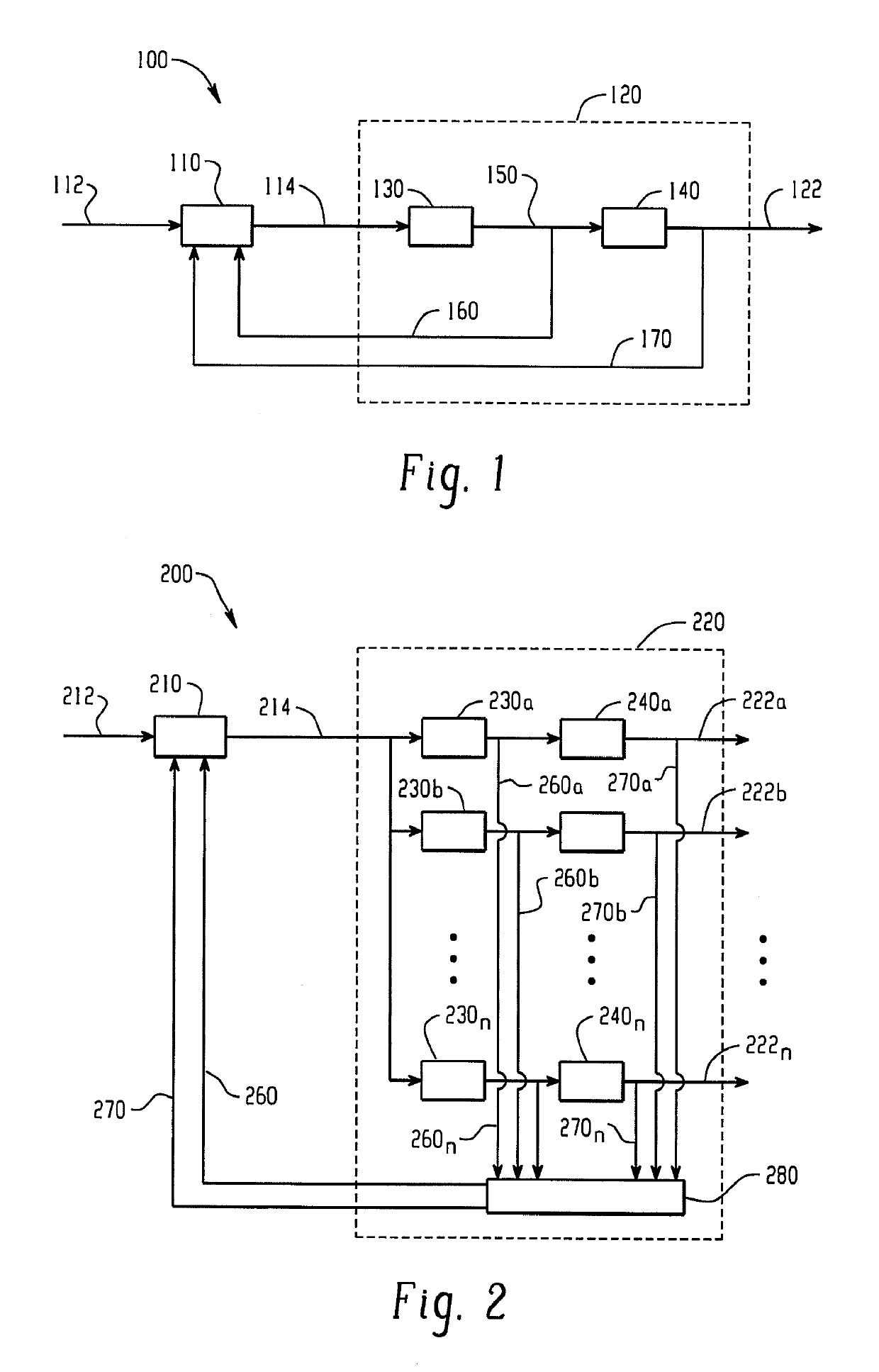
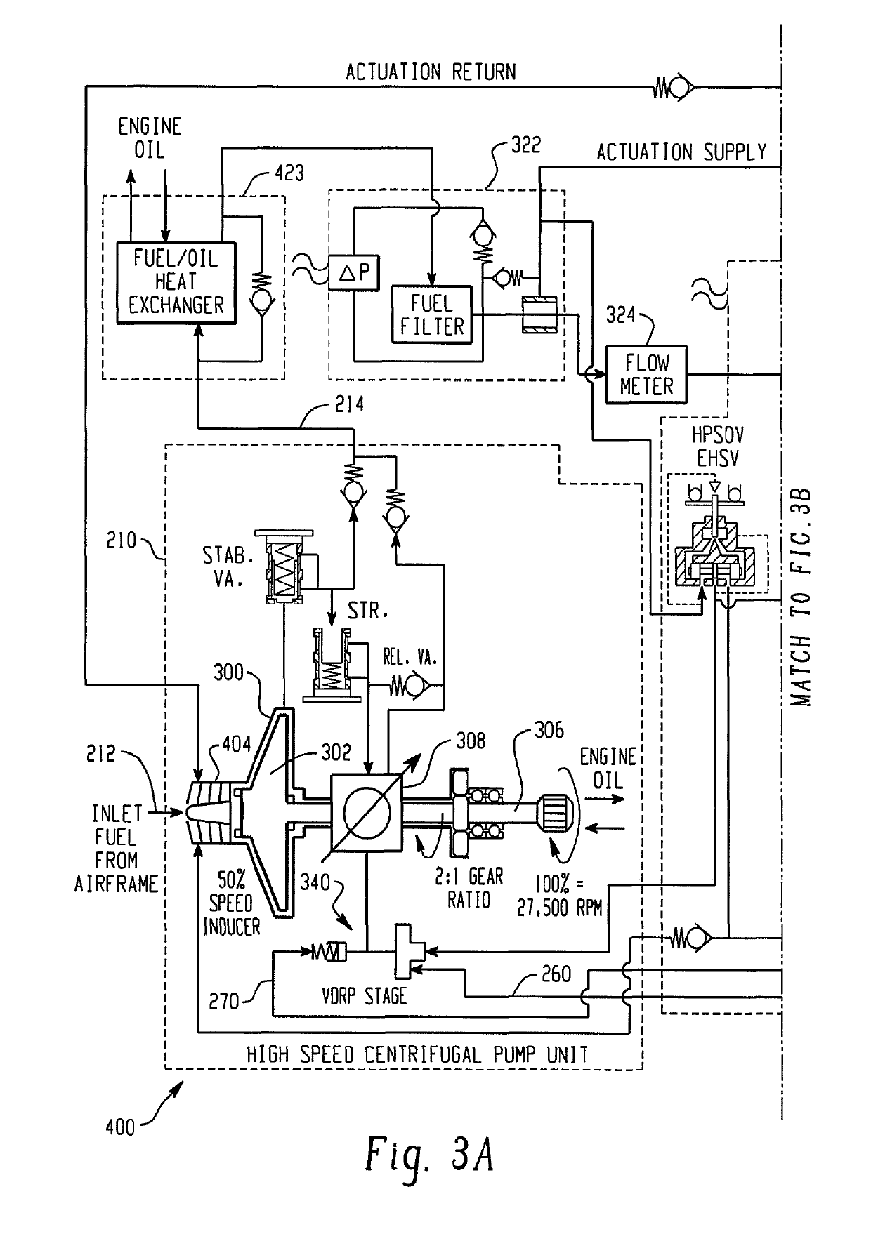
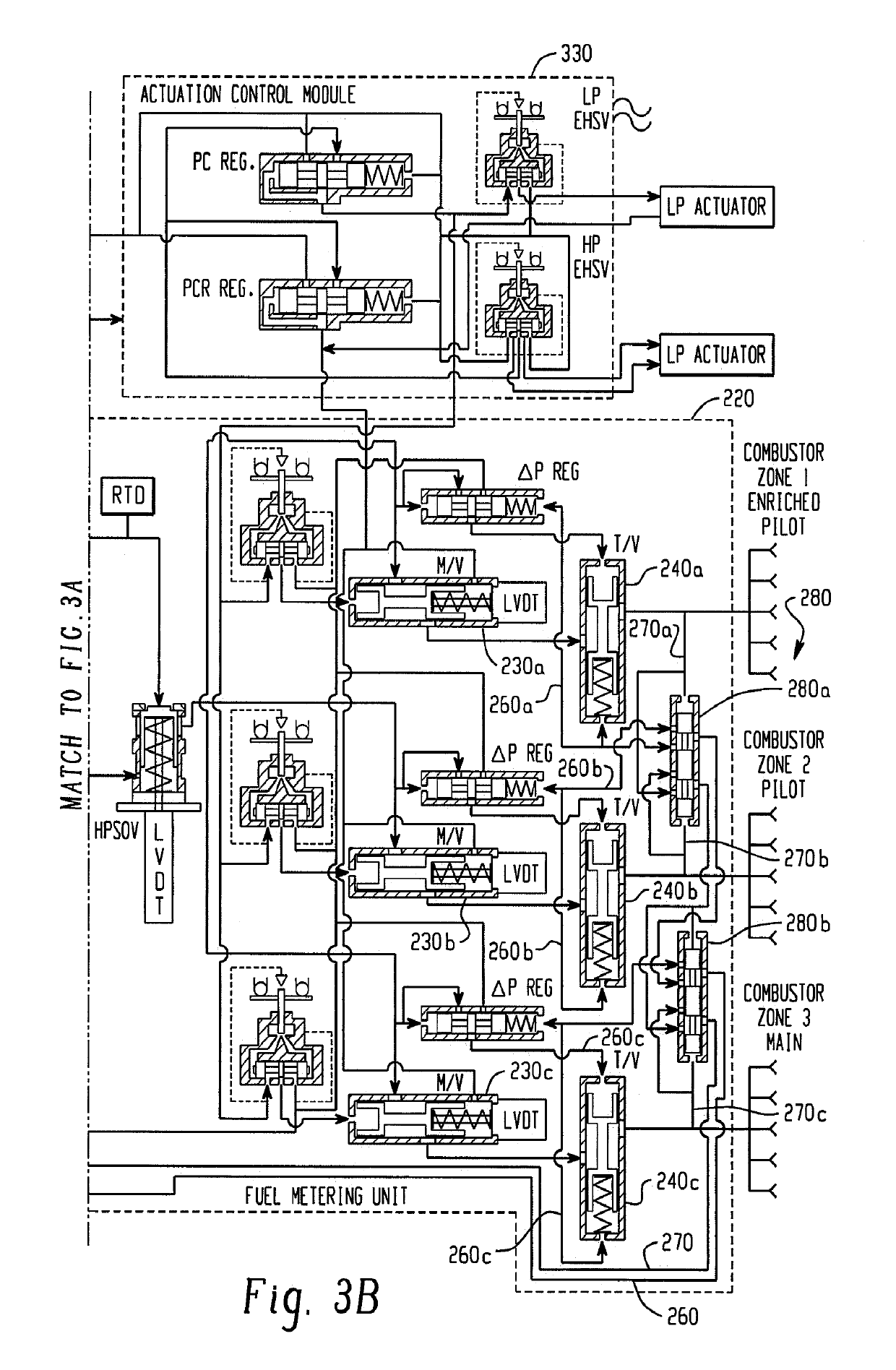
[0028]FIG. 1 is a schematic representation of a pumping and metering system 100, and in particular is representative of a single metering loop. The system 100 includes a pump unit 110 such as a fuel pump for an aircraft engine that receives fluid from an upstream source (not shown) as represented by reference numeral 112 and delivers pressurized fluid 114 to a downstream fuel control 120 that controls fluid for one or more downstream uses represented by reference numeral 122. In the broadest sense, the fuel control 120 includes a metering valve 130 and a throttling valve 140.

[0029]The metering valve 130 receives the pressurized fluid 114 from the pump unit 110 and meters or delivers pressurized fluid 150 downstream to the throttling valve 140. The pump unit 110, and typically one used as a fuel pump for an aircraft engine, for example, includes a centrifugal pump for the reasons noted in the Background. As further described above, additional use of a variable displacement pump is al...


PUM


Abstract

A pump assembly includes a pump unit having a centrifugal pump and a variable pump supplying pressurized flow. A fuel control assembly receives flow from the pump unit and includes at least one metering valve and at least one throttling valve. A control for the variable pump receives first and second pressure signals indicative of a pressure differential across the throttling valve, or across the metering valve / throttling valve combination, for altering operation of the variable pump in response to the pressure differential.

Description

BACKGROUND[0001]The present exemplary embodiment relates to a pump system, and more particularly to a system that includes a high speed centrifugal pump and a variable displacement pump. It finds particular application in conjunction with a fuel metering system, and will be described with particular reference thereto. However, it is to be appreciated that the present exemplary embodiment is also amenable to other like applications.[0002]Generally, a high speed centrifugal pump is desired in a pump system because of the benefits related to power consumption. Further, the centrifugal pump is generally lightweight, is deemed to have an extended life, has limited pressure ripple, and is generally conducive for a wide array of downstream uses. When trying to apply high-speed centrifugal pump technology in connection with fuel pumps associated with aircraft engine applications, for example, certain conditions need attention. Engine start is one area because the high speed centrifugal pump...

Claims


Application Information

Patent Timeline
Patent Type & Authority Patents(United States)
IPC IPC(8): G05D16/16F04B23/10F04B49/08F04D13/12F04B23/14
CPCF04B49/08F04B23/10F04B23/14F04D13/12G05D16/16Y10T137/86002Y10T137/0396
Inventor NYZEN, ROBERTCLEMENTS, MARTIN A.
Owner EATON INTELLIGENT POWER LTD
Learn More