Lighting system with ceramic socket arrangement

a technology of ceramic sockets and light fixtures, which is applied in the direction of one-pole connections, lighting and heating apparatus, coupling device connections, etc., can solve the problems of posing great safety hazards, and reducing the service life of the light fixture, so as to minimize the risk of safety hazards and maximize structural integrity

Active Publication Date: 2019-10-15
MJ MFGR DIRECT LLC
View PDF2 Cites 0 Cited by
  • Summary
  • Abstract
  • Description
  • Claims
  • Application Information

AI Technical Summary

Benefits of technology

[0008]Certain variations of the present invention provide a lighting system which is capable of minimizing the risk of safety hazard and maximizing structural integrity and convenience of the lighting system as a whole.

Problems solved by technology

There exist a number of disadvantages for the above-mentioned conventional lighting fixture.
First, the lighting fixture is primarily used for providing high-intensity illumination for an extended period of time.
As a result, when the illuminating device is turned on, the temperature of the illuminating device and the electrical sockets will rise very rapidly and will become very high.
This obviously poses great safety issues.
This safety problem worsens when one realizes that the electrical sockets can only be manufactured by insulating materials, such as plastic material.
While plastic material is a good electrical insulator, it cannot withstand high temperature caused by the operation of the illuminating device.
On the other hand, the electrical sockets cannot be manufactured by metallic materials because doing so would substantially increase the risks of short circuit and electrical fire.
Second, for conventional lighting fixtures such as the one described above, it is very difficult and troublesome to mount the illuminating device in the reflector housing.
It usually requires complicated procedures and may not be done in a short period of time.
As a result, when a user needs to replace the illuminating device, he or she may not have the necessary skill and may even need to find somebody else to finish the task.

Method used


Image

  • Lighting system with ceramic socket arrangement
  • Lighting system with ceramic socket arrangement
  • Lighting system with ceramic socket arrangement

Examples


Embodiment Construction

[0036]The following detailed description of the preferred embodiment is the preferred mode of carrying out the invention. The description is not to be taken in any limiting sense. It is presented for the purpose of illustrating the general principles of the present invention.

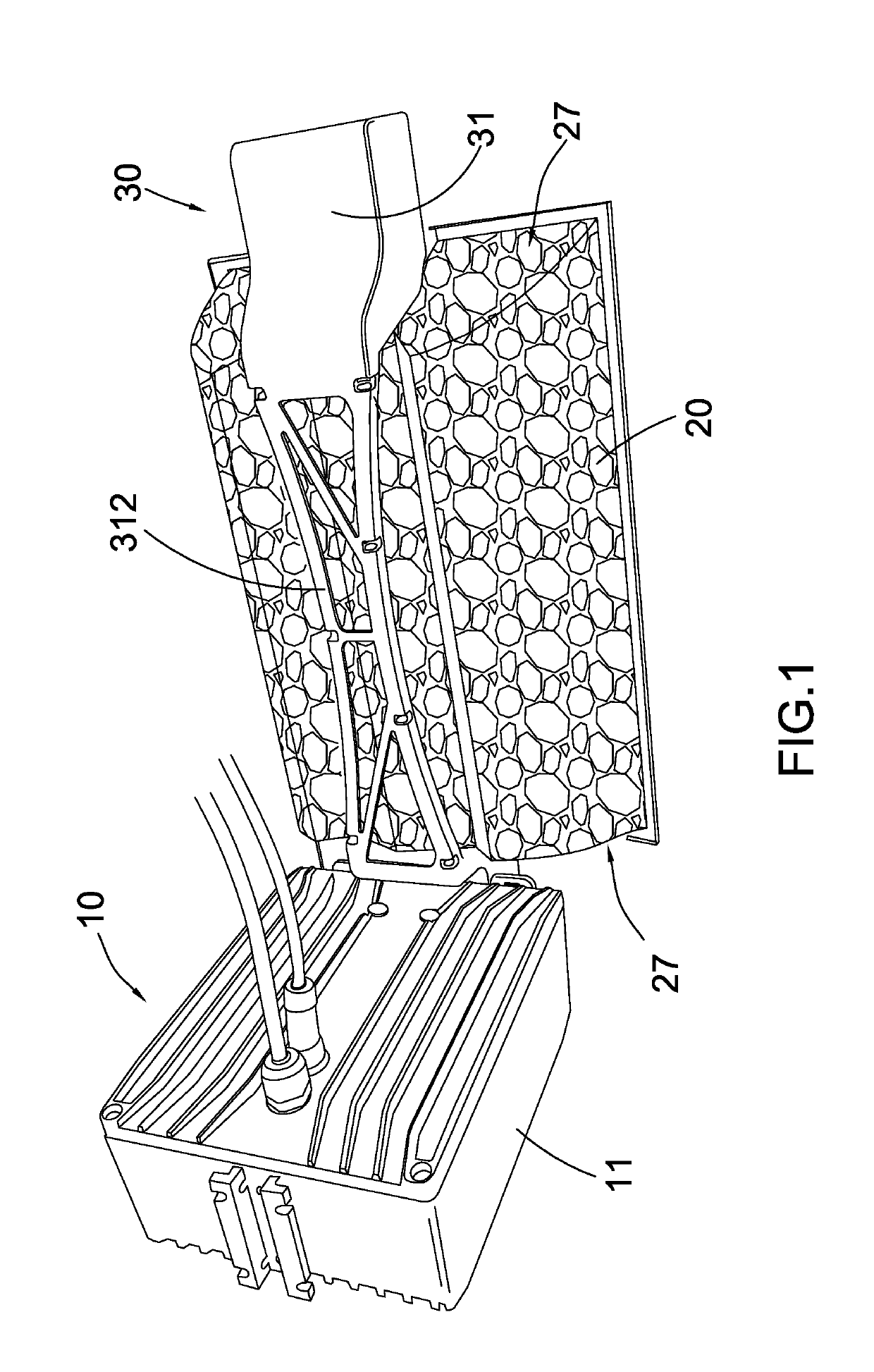
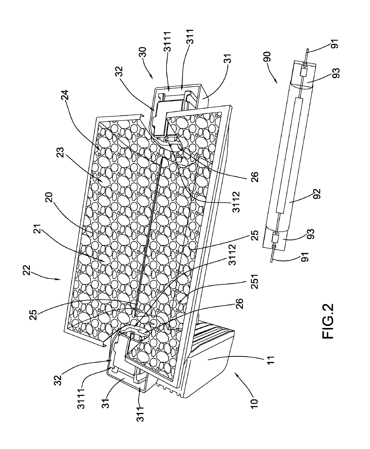
[0037]Referring to FIG. 1 to FIG. 9 of the drawings, a lighting system according a preferred embodiment of the present invention is illustrated. Broadly, the lighting system may comprise an electrical arrangement 10, a reflector housing 20, and a ceramic socket arrangement 30. The lighting system may be used in conjunction with an illuminating element 90 having an electrical terminal 91.

[0038]The electrical arrangement 10 may comprise an electrical housing 11 having a receiving cavity, and a power assembly 12 received in the electrical housing 11.

[0039]The reflector housing 20 may have an illuminating cavity 21 for receiving the illuminating element 90, and a reflector opening 22 for communicating the illuminati...


PUM


Abstract

A lighting system includes an electrical arrangement, a reflector housing and a ceramic socket arrangement. The ceramic socket arrangement includes at least one socket housing and at least one sliding connector received in the socket housing. The sliding connector includes a resilient terminal, a base configured from ceramic material and having an engagement track adapted for accommodating the electrical terminal of the illuminating element, and a sliding member configured from ceramic material and connected to the base in a slidably movable manner. The sliding member is arranged to slide between an unlocked position and a locked position. In the unlocked position, the sliding member is slid to expose the engagement track to an exterior of the sliding connector. In the locked position, the sliding member is slid and retained to cover the engagement track and to electrically connect the resilient terminal to the electrical terminal of the illuminating element.

Description

BACKGROUND OF THE PRESENT INVENTIONField of Invention[0001]The present invention relates to lighting apparatus, and more particularly to a lighting system comprising a ceramic socket arrangement which is capable of minimizing the risk of safety hazard and maximizing structural integrity and convenience of the lighting system as a whole.Description of Related Arts[0002]A conventional lighting fixture, such as a high-voltage grow light, usually comprises a power box, a reflector housing having a rectangular cross-sectional shape, and an illuminating device mounted in the reflector housing for providing high-intensity and a wide spectrum of illumination toward a predetermined area. The power box usually comprises electrical components for providing power to and activating the illuminating device.[0003]The lighting fixture usually comprises two electrical sockets provided on two ends of the reflector housing so that the illuminating device can be mounted on the reflector housing through...

Claims


Application Information

Patent Timeline
Patent Type & Authority Patents(United States)
IPC IPC(8): H01R33/22F21V19/00F21V7/22H01R13/717
CPCF21V7/22F21V19/0005F21V23/023H01R13/193H01R33/09H01R2101/00H01R13/717H01R33/22H01R2201/00
Inventor REN, RICHARDTRAN, JENNYTRAN, CONNIE
Owner MJ MFGR DIRECT LLC
Why Eureka
Try Eureka