
Hand held appliance

a technology for hand-held appliances and motors, which is applied in the field of motor mounts, can solve the problems that motors can form a significant part of weight, and achieve the effect of reducing efficiency

Inactive Publication Date: 2019-10-15
DYSON TECH LTD
View PDF74 Cites 23 Cited by
  • Summary
  • Abstract
  • Description
  • Claims
  • Application Information

AI Technical Summary

Benefits of technology

[0007]The projections are provided to reduce the transmission of vibration / noise from a motor through the motor mount.
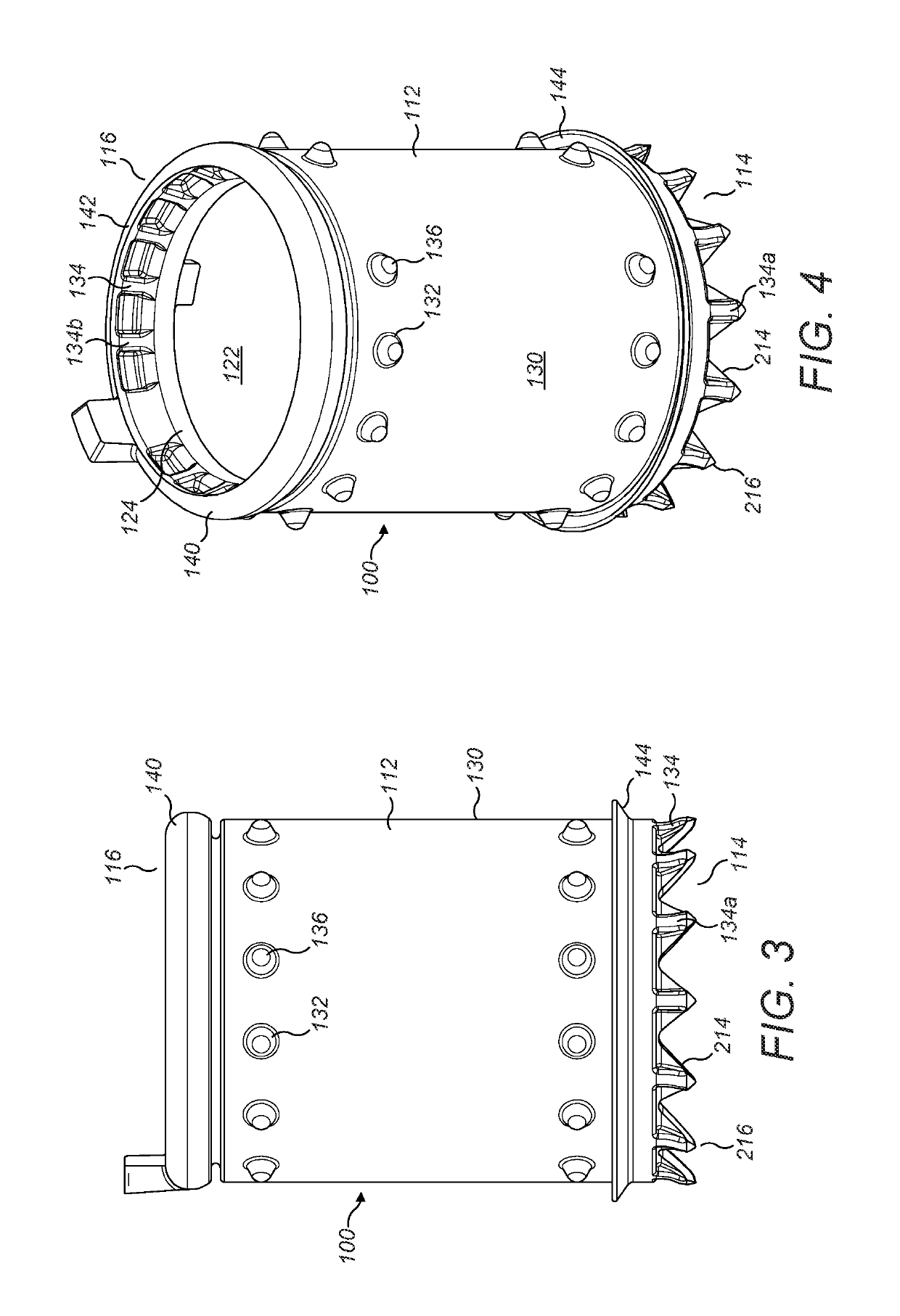
[0021]The projections and the motor are orientated such that when the motor is activated the resultant pressure presses down on the first end of the motor mount. Having projections reduces the contact surface of the motor mount with the casing thereby reducing the transmission of vibration / noise from the motor through the motor mount and to the casing.
[0025]It is preferred that a fluid flow path is provided between the fluid inlet and fluid outlet and through the sleeve. The annular seal of the motor mount seals the fluid flow path with respect to the casing preventing flow recirculating around the motor mount which reduces efficiency.

Problems solved by technology

However, particularly in the case of hand held appliances, the motor can form a significant part of the weight of the appliance and if that appliance is dropped the motor must be protected from damage and dislocation from its' housing.

Method used


Image

  • Hand held appliance
  • Hand held appliance
  • Hand held appliance

Examples


Embodiment Construction

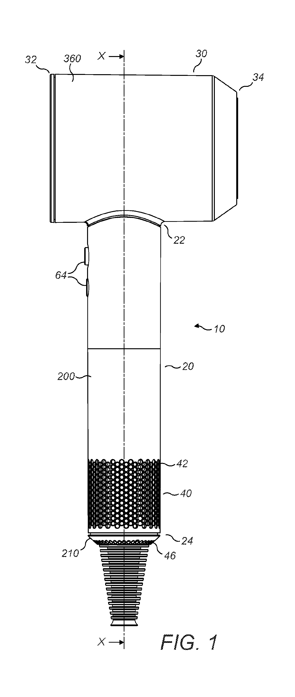
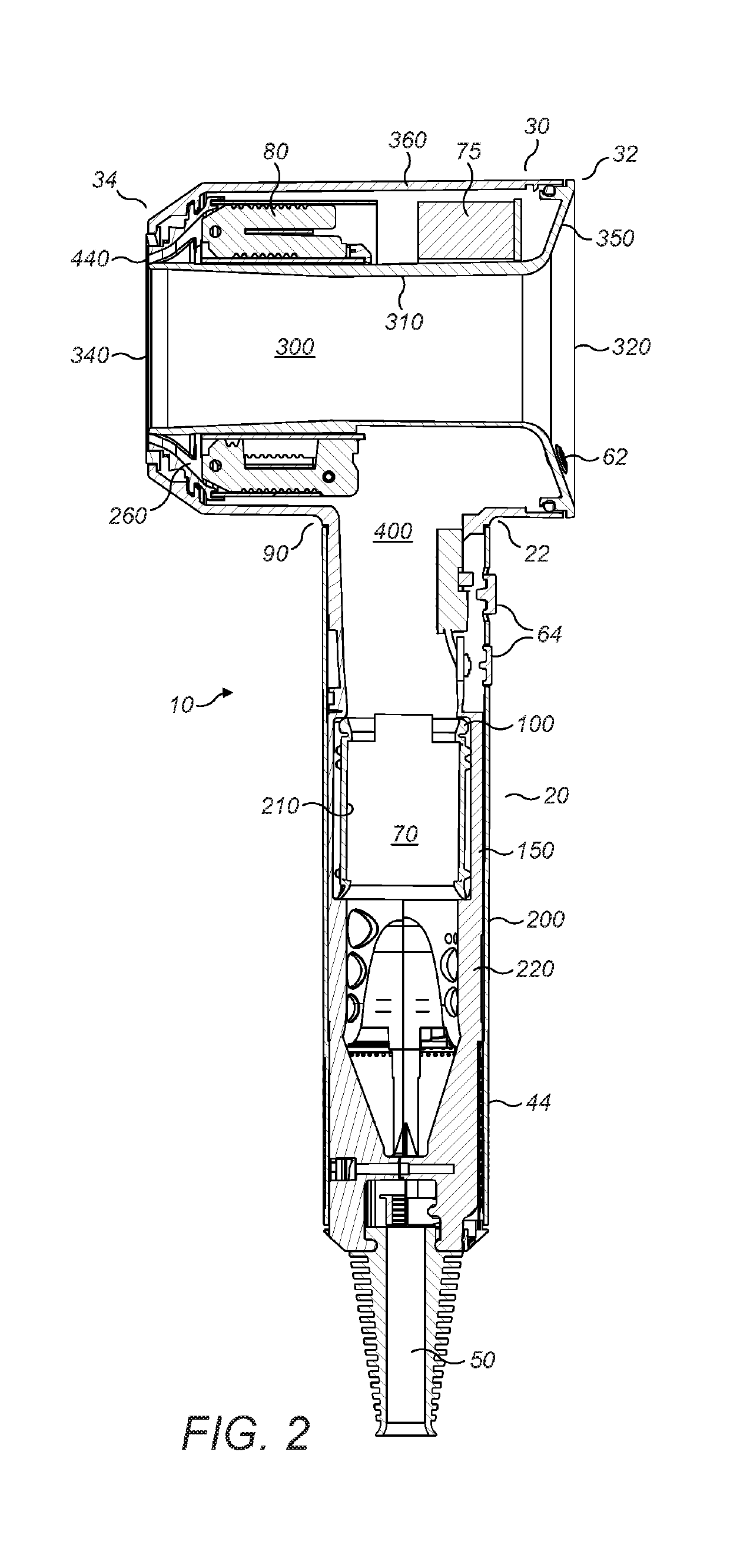
[0034]FIGS. 1 and 2 show a hairdryer 10 with a handle 20 and a body 30. The handle has a first end 22 which is connected to the body 30 and a second end 24 distal from the body 30 and which includes a primary fluid inlet 40. Power is supplied to the hairdryer 10 via a cable 50. At a distal end of the cable 50 from the hairdryer 10 a plug (not shown) is provided, the plug may provide electrical connection to mains power or to a battery pack for example.

[0035]The handle 20 has an outer wall 200 which extends from the body 30 towards a distal end 24 of the handle. At the distal end 24 of the handle an end wall 210 extends across the outer wall 200. The cable 50 enters the hairdryer through this end wall 210. The primary fluid inlet 40 in the handle 20 includes first apertures that extend around and along 42 the outer wall 200 of the handle in a series of rows and / or columns that extend from the distal end 24 of the handle 20 and second apertures that extend across 46 and through the en...


PUM


Abstract

A mount for an electric motor, the mount comprising a sleeve for receiving a motor, the sleeve having a longitudinal axis extending between a first end and a second end, wherein the first end comprises a plurality of plurality of projections and the plurality of projections extend along the longitudinal axis. The sleeve may receive the motor via the first end or the second end. The plurality of projections may be spaced around a circumference of the sleeve. The plurality of projections may comprise a pattern of substantially constant frequency around the sleeve. The plurality of projections may be substantially V-shaped with the point extending along the longitudinal axis from the first end of the sleeve.

Description

REFERENCE TO RELATED APPLICATIONS[0001]This application claims the priority of United Kingdom Application No. 1518631.5, filed Oct. 21, 2015, the entire contents of which are incorporated herein by reference.FIELD OF THE INVENTION[0002]This invention relates to a mount for a motor, preferably an electric motor.BACKGROUND OF THE INVENTION[0003]Electric motors are becoming increasingly sophisticated and modern designs are capable of ever higher rotational speeds. One such design of electric motor is a brushless DC motor as used by the applicant in its range of handheld vacuum cleaners and which is capable of being driven at rotational speeds in the region of 100 Krpm.[0004]The use of high speed motors in fluid-moving applications such as vacuum cleaners, fans and hair care appliances is technically attractive since a fan unit equipped with a physically small motor can nonetheless produce very high fluid flow rates.[0005]However, particularly in the case of hand held appliances, the mo...

Claims


Application Information

Patent Timeline
Patent Type & Authority Patents(United States)
IPC IPC(8): F26B11/02A45D20/12A45D20/10H02K5/24F24H3/04
CPCA45D20/10A45D20/12H02K5/24F24H3/0423A47L9/22A45D20/00
Inventor BLANC, JEAN-BAPTISTE JEROMEDOUGLAS, CRAIGATKINSON, ANTOINE FRANCOIS
Owner DYSON TECH LTD
Learn More