
Laparoscopic suture device with impulse deployment

a laparoscopic and suture technology, applied in the field of sutures and suturing devices, can solve the problems of irritation or pain of patients, dislodged from the abdominal wall, and difficult to position the end of the laparoscopic device squarely against the inner wall of the abdomen

Active Publication Date: 2019-10-08
SURGIMATIX
View PDF12 Cites 1 Cited by
  • Summary
  • Abstract
  • Description
  • Claims
  • Application Information

AI Technical Summary

Problems solved by technology

However, due to several factors, such as the relatively rigid and elongated nature of the laparoscopic tacker, the limited locations and number of access ports available, and the typical location of hernia defects, it is difficult to position the end of the laparoscopic device squarely against the inner wall of the abdomen.
Over time, especially in the case of metal, coil-shaped tacks, these tacks may cause irritation or pain to the patient, become dislodged from the abdominal wall, or cause other complications post-surgery.
However, absorbable tacks also tend to provide holding or tensile strength that is less than optimal.
Another problem encountered by surgeons while using conventional laparoscopic devices is the difficulty with which to finally deploy a given fastener into the desired region of tissue.
Due to the tough and / or fibrous nature of some types of tissue, it may be physically challenging to quickly and neatly release a fastener into the tissue while operating the fastening device by hand.
While such convenience features may facilitate fastener installation, these features also compromise the degree of control the surgeon has over the installation process.
En particular, these convenience features tend to perform both the insertion and the release actions too quickly, suddenly and / or discretely, thereby limiting tactile feedback to the surgeon and resulting in an undesirable disconnect from the fastening process.
Also, depending on the force or speed with which such convenience features insert or release fasteners, there is a potential for tissue trauma or bleeding.

Method used


Image

  • Laparoscopic suture device with impulse deployment
  • Laparoscopic suture device with impulse deployment
  • Laparoscopic suture device with impulse deployment

Examples


Embodiment Construction

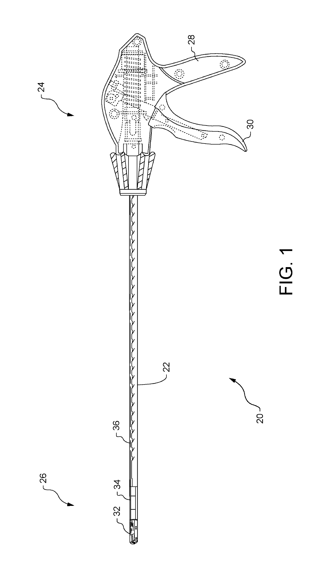
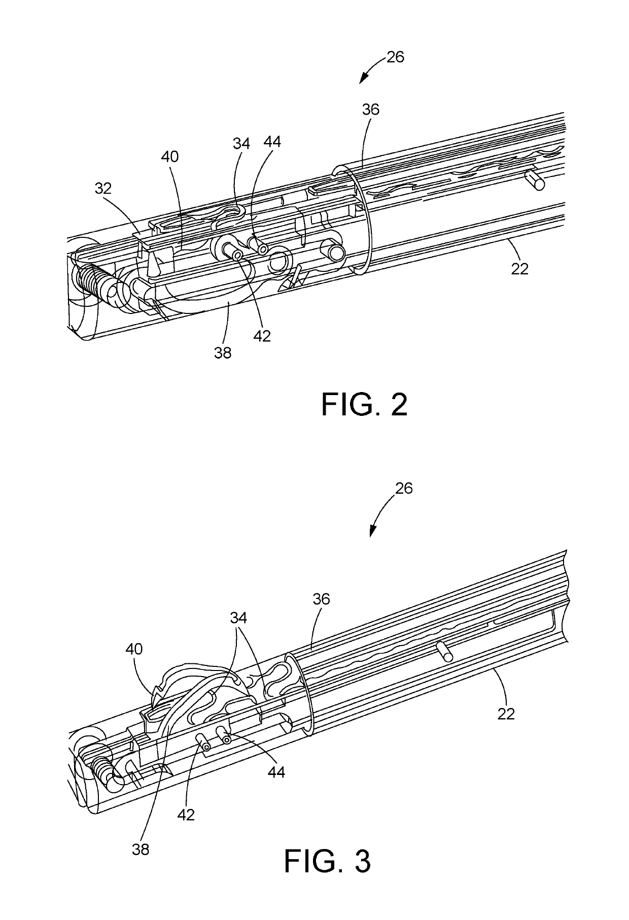
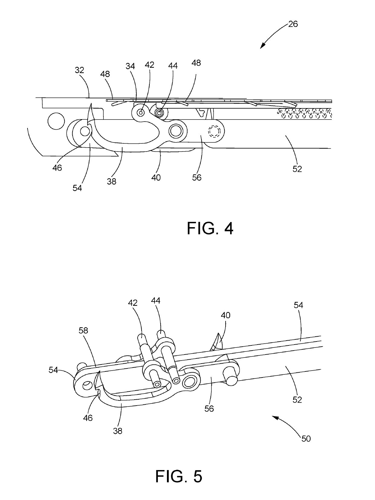
[0032]Referring now to the drawings, and with specific reference to FIG. 1, a medical fastening or suturing device constructed in accordance with the teachings of the present disclosure is generally referred to by reference numeral 20. The suturing device 20, as will be described in further detail herein, may advantageously enable convenient yet effective means of providing fasteners within a surgical environment. The disclosed embodiments may additionally facilitate the installation and deployment of fasteners or sutures during minimally invasive surgical procedures, such as laparoscopic procedures, and the like, without compromising control over the installation and deployment processes. As used for laparoscopic treatment of a hernia, the embodiment of FIG. 1, for example, may be employed to reach beneath sections of tissue, within or around the abdominal region, to fasten tissues of the abdominal wall or to fasten prosthetic mesh to the abdominal wall from the inside. Although th...


PUM


Abstract

A suturing device is provided. The suturing device may include at least one suturing needle, a drive mechanism and an impulse mechanism. The drive mechanism may be operatively coupled to the suturing needle and configured to advance the suturing needle from a retracted position to an extended position during engagement, and retract the suturing needle from the extended position to the retracted position during disengagement. The impulse mechanism may be operatively coupled to the drive mechanism and configured to accumulate energy during engagement of the suturing needle, and instantaneously release the accumulated energy through the drive mechanism during disengagement.

Description

CROSS-REFERENCE TO RELATED APPLICATION[0001]This application is based on and claims priority to International Application Serial No. PCT / US15 / 68025, filed on Dec. 30, 2015, which claims priority to U.S. Provisional Application No. 62 / 097,882 filed on Dec. 30, 2014.FIELD OF THE DISCLOSURE[0002]The present disclosure generally relates to medical fastening devices, and more particularly, relates to sutures and suturing devices for fastening tissue and / or prosthetic material.BACKGROUND OF THE DISCLOSURE[0003]The fastening of tissues has long been a need in the medical industry, and correspondingly, a finite number of fastening devices have been developed for different applications and uses. Among these devices are laparoscopic fastening devices or tackers which are often used with minimally invasive procedures such as laparoscopic repair of hernias, and the like. A typical laparoscopic procedure involves the insertion of thin, elongated instruments into relatively small incisions or acc...

Claims


Application Information

Patent Timeline
Patent Type & Authority Patents(United States)
IPC IPC(8): A61B17/04A61B17/062A61B17/06
CPCA61B17/0469A61B17/0625A61B17/0485A61B17/06004A61B2017/06076A61B2017/0608A61B2017/06042
Inventor HASAN, JAFAR S.CHIN, WAI N.ORRICO, JAMESSABAN, ADAM A.KOBYLEWSKI, GARY M.
Owner SURGIMATIX
Learn More