
Inspection system and inspection method

a technology of inspection system and inspection method, applied in the field of inspection, can solve the problem of difficulty for users to easily determine what reference information to use, and achieve the effect of easy determination

Active Publication Date: 2019-10-01
KOHYOUNG TECH
View PDF15 Cites 2 Cited by
  • Summary
  • Abstract
  • Description
  • Claims
  • Application Information

AI Technical Summary

Benefits of technology

The patent is about a system that can process an image of an inspection object and determine if it is good or defective. This system can also display the processed image with reference information that helps users determine which information is suitable or not suitable for the inspection object. This makes it easier for users to quickly determine if the inspection object is good or defective.

Problems solved by technology

As a result, there was a problem in that it was difficult for a user to easily determine what reference information was accountable for an inspection object being determined to be good or defective, only through the inspection results (that is, good or defective) displayed on the output unit.

Method used


Image

  • Inspection system and inspection method
  • Inspection system and inspection method
  • Inspection system and inspection method

Examples


first embodiment

[0033]FIG. 1 is a view schematically showing an inspection system according to a first embodiment of the present disclosure. Referring to FIG. 1, an inspection system 100 according to the present embodiment includes a data acquisition unit 110.

[0034]The data acquisition unit 110 irradiates light on an inspection object IO, and receives light reflected by the inspection object to acquire image data of the inspection object. In the present embodiment, the inspection object includes a solder joint which is a junction portion of a component of a printed circuit board and solder, but may not be limited thereto.

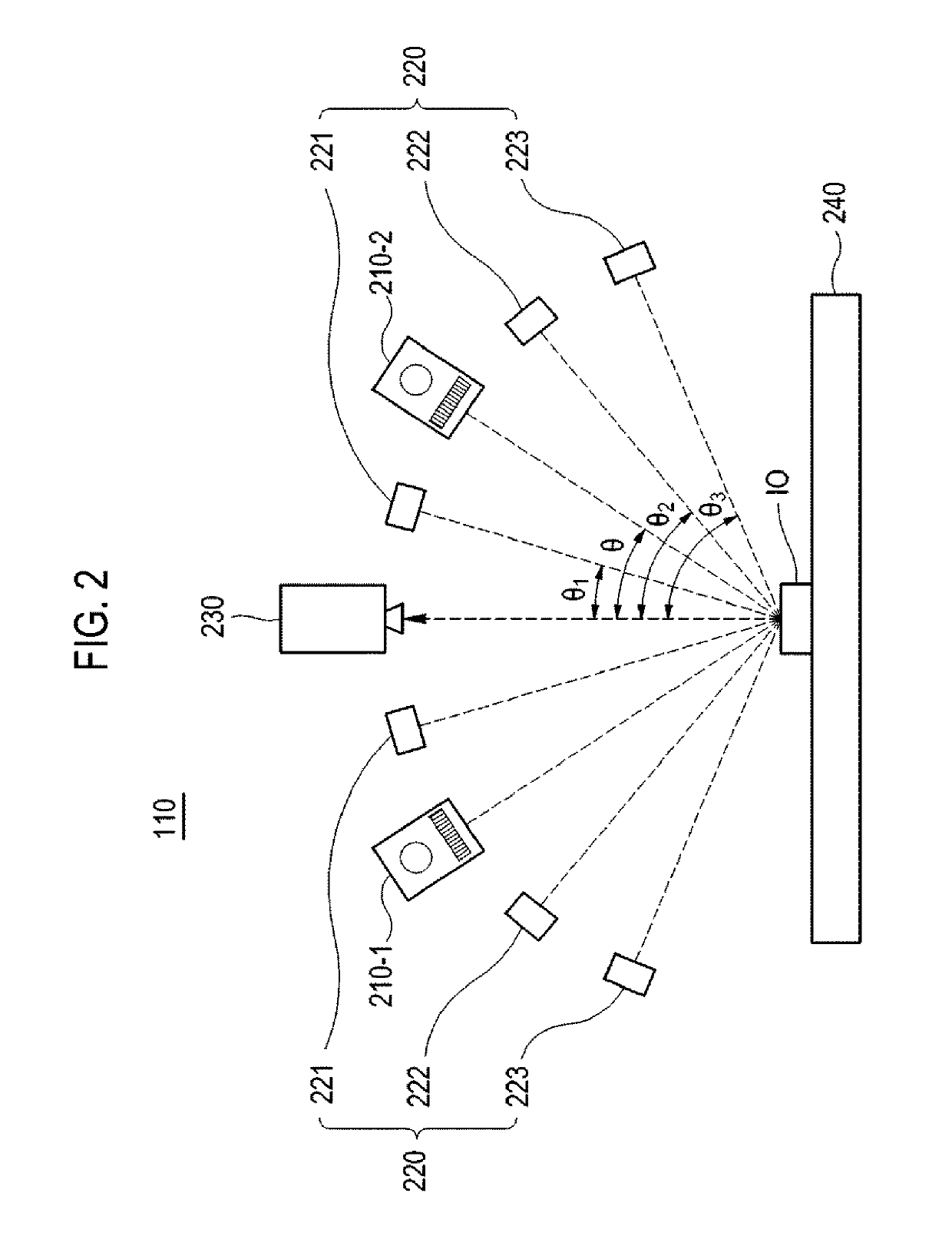
[0035]FIG. 2 schematically shows the data acquisition unit 110 according to the first embodiment of the present disclosure. Referring to FIG. 2, the data acquisition unit 110 includes projection units 210-1 and 210-2. The projection units 210-1 and 210-2 irradiate the inspection object IO with pattern illumination for acquiring first image data of the inspection object IO. The firs...

second embodiment

[0072]FIG. 13 is a block diagram schematically showing the configuration of an inspection system 1300 according to a second embodiment of the present disclosure. In this embodiment, the same components as those of the first embodiment are denoted by the same reference numerals and description thereof will be omitted.

[0073]Referring to FIG. 13, the inspection system 1300 includes a storage unit 1320. The storage unit 1320 stores reference information for determining whether an inspection object is good or defective. In the present embodiment, the inspection object includes a rear case for a mobile phone made of plastic or metal, but may not be limited thereto. In addition, the storage unit 1320 may store image data of the inspection object acquired by the data acquisition unit 110.

[0074]In an embodiment, the reference information includes a reference value for determining whether each of a height, a width, and a slope of the inspection object IO is good or defective. The reference va...


PUM

PropertyMeasurementUnit
inclination angle θ1aaaaaaaaaa
height inspectionaaaaaaaaaa

Abstract

Disclosed are an inspection system and an inspection method of performing image processing on an outline of an inspection object according to whether the inspection object is good or defective, and overlapping and displaying the image-processed outline with reference information for determining whether the inspection object is good or defective. The inspection system includes: a data acquisition unit configured acquire an image of an inspection object by irradiate light on the inspection object; a processing unit configured to detect an outline of the inspection object based on the image data of the inspection object; and an output unit configured to overlap and display the outline with reference information, wherein the processing unit is configured to determine whether the outline is good or defective based on the reference information to perform image processing on the outline according to whether the outline is good or defective.

Description

TECHNICAL FIELD[0001]The present disclosure relates to the inspection field, and more particularly, to an inspection system and a method of inspecting whether an inspection object is good or defective.BACKGROUND ART[0002]In recent years, as consumer standards for product quality have increased day by day, manufacturers are making efforts to eliminate defective products during production processes, assembly processes, intermediate processes, and final assembly completion processes in producing their products. In order to eliminate defective products, various inspection systems have been used to inspect whether the corresponding products are good (GOOD or PASS) or defective (NG).[0003]Generally, an inspection system irradiates a product, that is, an inspection object, with patterned light generated by a projection unit, and receives light reflected from the inspection object in an imaging unit to acquire an image of the inspection object. In addition, the inspection system performs in...

Claims


Application Information

Patent Timeline
Patent Type & Authority Patents(United States)
IPC IPC(8): G06T7/00G01B11/25G01B11/06G01N21/956G01B11/02H05K1/02G05B19/418H05K3/34G06T7/62G01N21/88
CPCG01B11/02G01N21/95684H05K3/3478G01N21/8851H05K1/0269G01B11/2527G05B19/41875G06T7/0004G01B11/25G06T7/001G06T7/62G01B11/0608H05K2203/163G06T2207/10052G06T2207/30152G01N2021/95646G01N2021/8887G01N2021/95615G06T2207/30108
Inventor SEO, SEUNG AEAHN, WON MILEE, HYE INLEE, JONG HUI
Owner KOHYOUNG TECH
Learn More