Backfeed stage, radial turbo fluid energy machine

a technology of radial turbo and fluid energy machine, which is applied in the direction of non-positive displacement fluid engine, radial flow pump, pump components, etc., can solve the problems of comparatively loss-impaired throughflow and space-consuming, and achieve the effect of low loss

Inactive Publication Date: 2019-09-24
SIEMENS ENERGY GLOBAL GMBH & CO KG
View PDF7 Cites 0 Cited by
  • Summary
  • Abstract
  • Description
  • Claims
  • Application Information

AI Technical Summary

Benefits of technology

[0006]Starting from the problem and disadvantages of the prior art, the invention is set upon the task of developing a backfeed stage of the type defined in the introduction in such a way that a less space-consuming backfeed stage creates a less loss-impaired flow.
[0011]The backfeed stage according to the invention, as a consequence of the first guide vane and second guide vane which are arranged in series in the flow direction, is less space-consuming than a backfeed stage which does not have the two guide vane stages in series. An alignment of the flow with the inlet into the impeller following downstream is aerodynamically more efficient by means of the staged guide vane design.
[0012]The second guide vane stage according to the invention which is offset in the circumferential direction or the arrangement of the second guide vanes in the circumferential direction asymmetrically to the trailing edges of the first guide vanes leads to a reduction of the aerodynamic losses of the process fluid in the throughflow of the backfeed stage.
[0013]The realignment and deflection of the process fluid downstream of the exit from the impeller toward the inlet of the impeller following downstream is particularly low in losses and low in space consumption according to the invention. The bend length, which in the circumferential direction characterizes the distance between the two trailing edges of adjacent first guide vanes, is divided by the radial line through the leading edge of the second guide vanes which are arranged between the two first vanes in the circumferential direction into a pressure-side section and a suction-side section.
[0015]It has been shown that the division of the bend length, which in the circumferential direction characterizes the distance between the two trailing edges of adjacent first guide vanes is particularly advantageous if the ratio of the suction-side section to the overall bend length lies between 0.2 and 0.4. This characteristic offset toward the suction side of a first guide vane, which defines the flow passage in the circumferential direction, leads to a turbulence-free and less separation-impaired throughflow, which is particularly low in losses.

Problems solved by technology

The arrangement which is known from the prior art is not very compact—therefore comparatively space-consuming—and the throughflow is comparatively loss-impaired.

Method used


Image

  • Backfeed stage, radial turbo fluid energy machine
  • Backfeed stage, radial turbo fluid energy machine
  • Backfeed stage, radial turbo fluid energy machine

Examples


Embodiment Construction

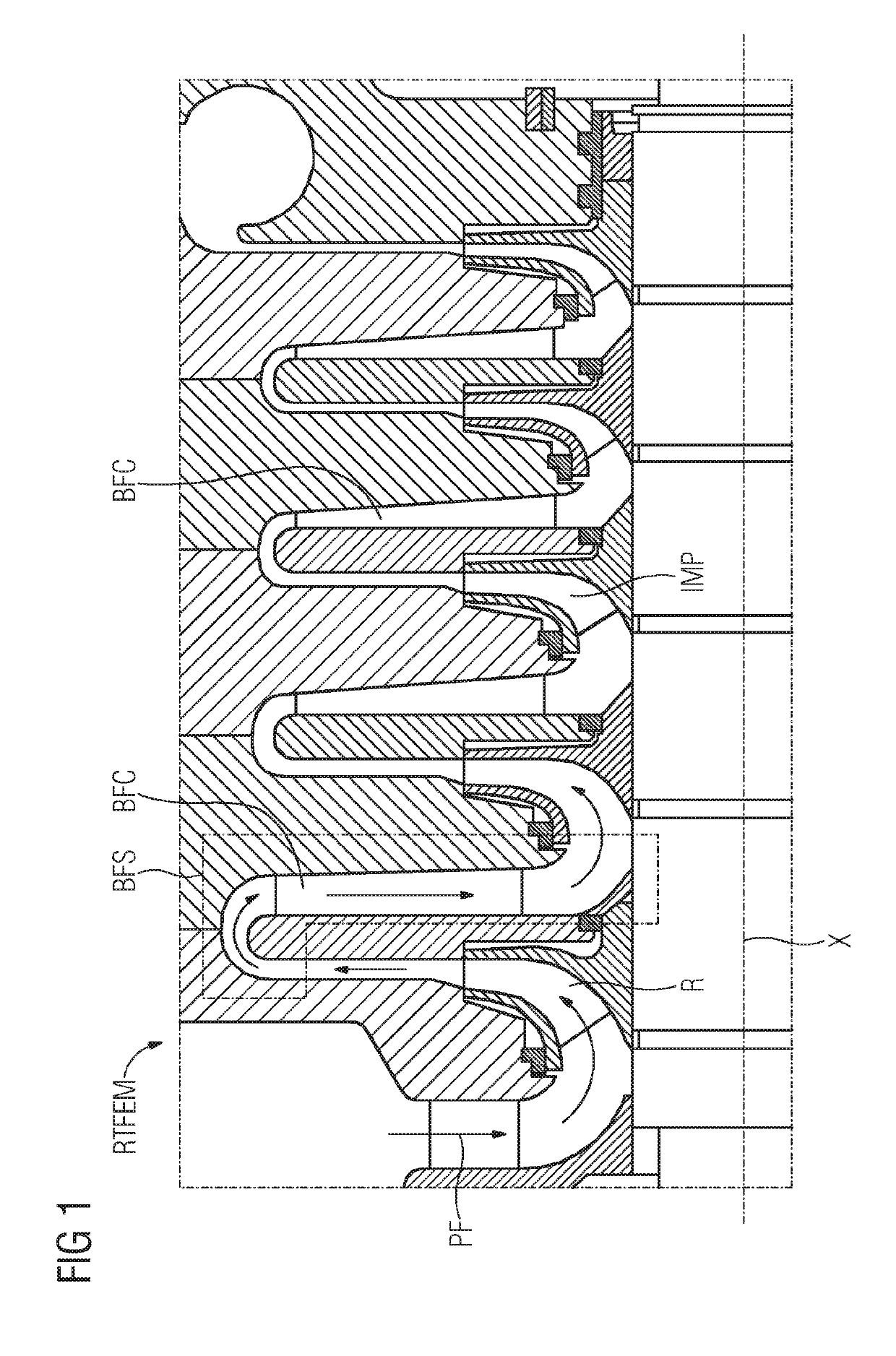
[0020]FIG. 1 shows a schematic representation of a longitudinal section of a radial turbo fluid energy machine RTFEM in the detail of a flow passage for a process fluid PF. The detail shows five impellers IMP which as a component part of a rotor R rotate around an axis X during operation. In reference to this axis X are all statements regarding this description, such as axial, radial, tangential or circumferential direction. The impellers IMP induct the process fluid PF axially in each case and transport this in an accelerated state radially outward. After exiting the impeller IMP, the process fluid PF makes its way into a backfeed stage BFS comprising a backfeed duct BFC.

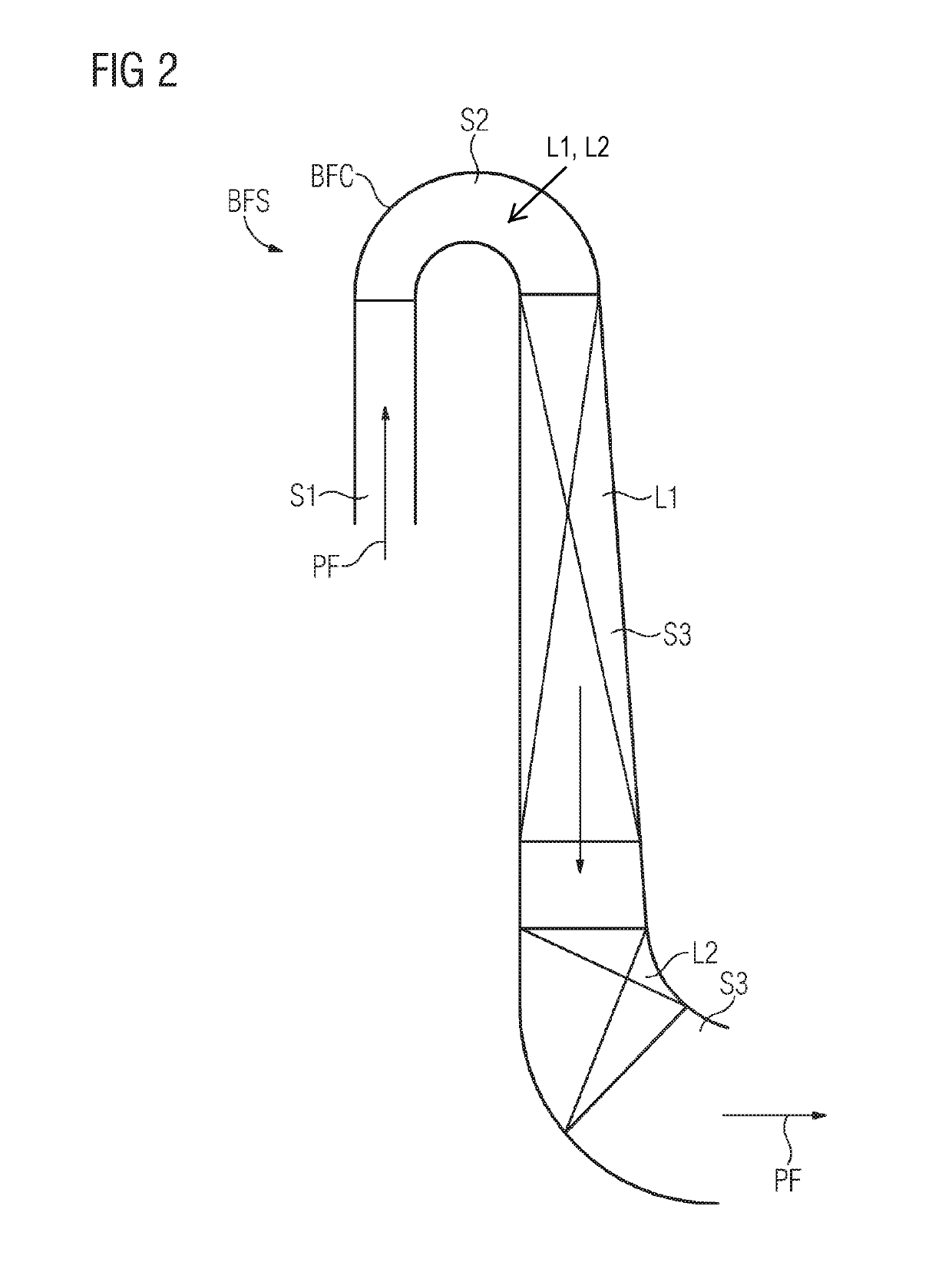
[0021]FIG. 2 shows the backfeed stage BFS or the backfeed duct BFC in detail. The process fluid PF makes its way out of the impeller IMP into a first section S1 of the backfeed duct, which is designed for conducting the process fluid PF radially outward. In the second section S2 located downstream, the process flui...


PUM


Abstract

A backfeed stage of a radial turbo fluid energy machine for deflecting a flow direction of a process fluid issuing from a rotor, rotating around an axis, from radially outward to radially inward, having a backfeed duct which has three adjacent sections in the flow direction, wherein a first section is designed for conducting the process fluid radially outward, wherein a second section is designed for deflecting the process fluid from the radially outward to radially inward direction, wherein a third section is designed for conducting the process fluid radially inward, wherein the second section and third section, or only the third section, have / has first guide vanes which define flow passages of the backfeed duct in relation to each other in the circumferential direction.

Description

CROSS REFERENCE TO RELATED APPLICATIONS[0001]This application is the US National Stage of International Application No. PCT / EP2017 / 054686 filed Mar. 1, 2017, and claims the benefit thereof. The International Application claims the benefit of German Application No. DE 102016203305.0 filed Mar. 1, 2016. All of the applications are incorporated by reference herein in their entirety.FIELD OF INVENTION[0002]The invention relates to a backfeed stage of a radial turbo fluid energy machine, especially of a radial turbocompressor for deflecting a flow direction of a process fluid issuing from a rotor, rotating around an axis, from radially outward to radially inward, comprising a backfeed duct which has three adjacent sections in the flow direction, wherein a first section is designed for conducting the process fluid radially outward, wherein a second section is designed for deflecting the process fluid from radially outward to radially inward direction, wherein a third section is designed f...

Claims


Application Information

Patent Timeline
Patent Type & Authority Patents(United States)
IPC IPC(8): F04D29/44F04D17/12F04D29/66F04D29/28F04D29/42F04D29/053
CPCF04D29/053F04D29/4213F04D17/122F04D29/444F04D29/284F04D29/666
Inventor HERMES, VIKTOR
Owner SIEMENS ENERGY GLOBAL GMBH & CO KG
Why Eureka
Try Eureka