
Mortar mixer paddle assembly for use with polyethylene drums and associated methods

a polyethylene drum and mixer technology, applied in the field of portable masonry mortar mixers paddles, can solve the problems of cleaning the mortar mixer, the difficulty of removing remaining unwanted cured mortar, and the masonry industry, and achieve the effect of removing the build-up of mortar mixture slurry

Active Publication Date: 2019-09-24
SWISHER JAMES A
View PDF4 Cites 3 Cited by
  • Summary
  • Abstract
  • Description
  • Claims
  • Application Information

AI Technical Summary

Benefits of technology

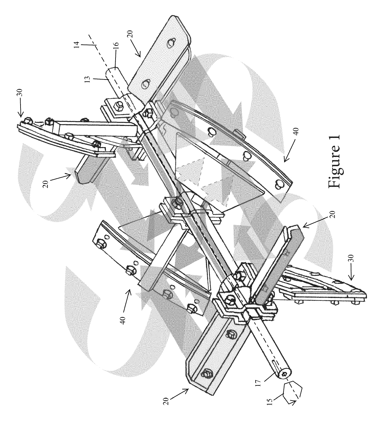
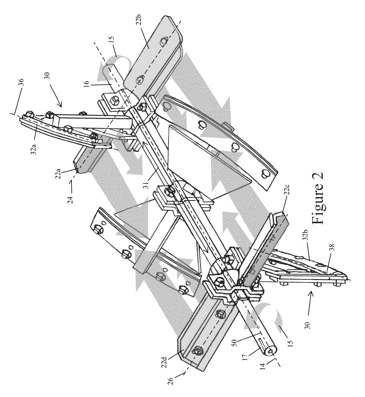
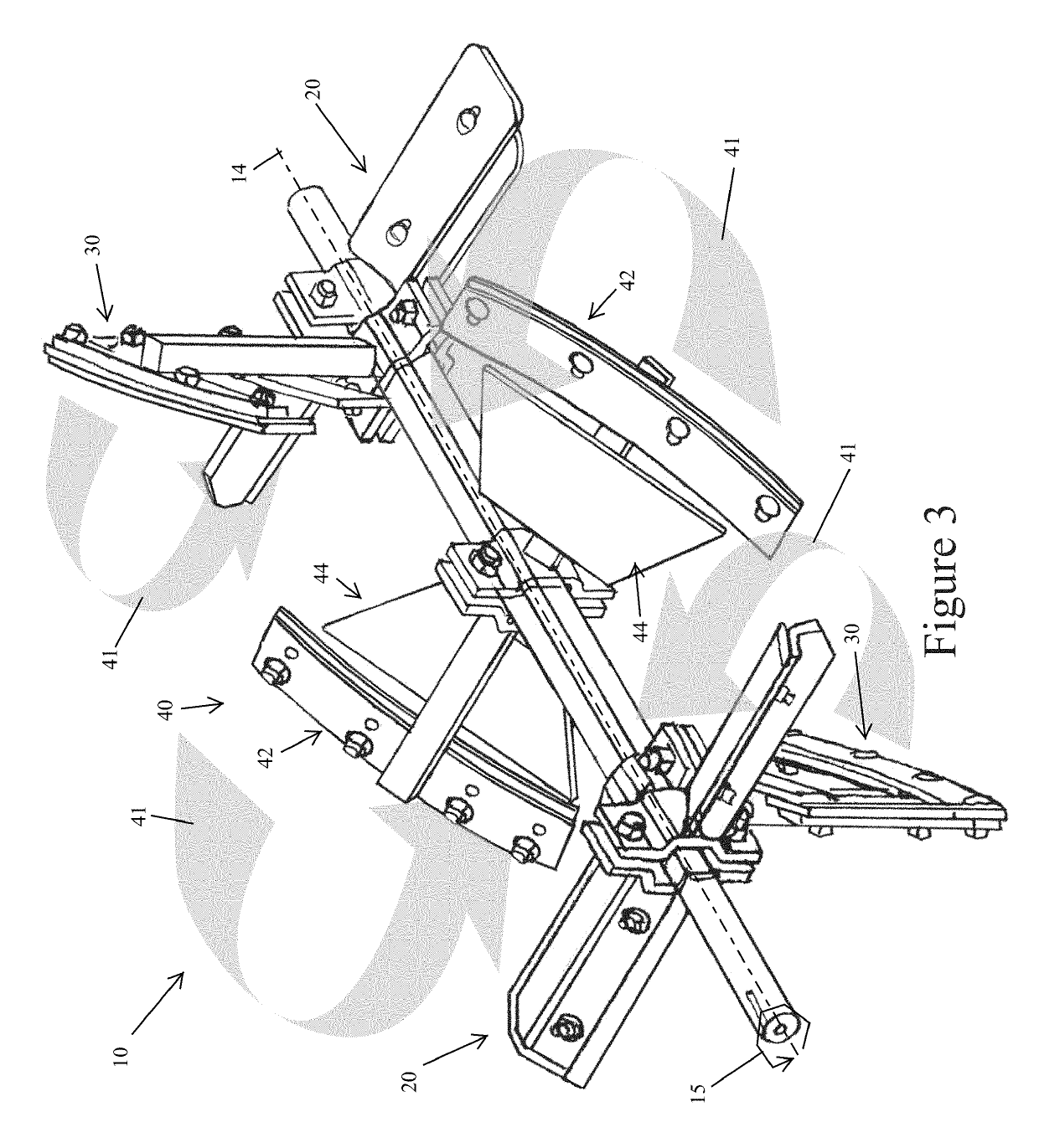
The patent is about a portable mortar mixer that operates at a slow speed and is designed to be easily cleaned on the job site. The mixer includes a paddle assembly with a centrally registered shaft that is positioned in a polyethylene drum. The paddle assembly includes a mechanism for entraining air into the mortar mixture and horizontally reciprocating the mixture in a bi-directional linear travel path. This prevents the formation of slurry buildup on the paddles and shaft. Additionally, there is a mechanism that can redirect the slow-moving mixture upwards into faster-moving arcuate paths rotating around the shaft, which further helps to minimize slurry buildup. The use of the portable mortar mixer produces consistent and creamy mortar with minimal slurry buildup on the paddles and shaft.

Problems solved by technology

Somehow, the masonry industry has remained, for the most part, unfamiliar with the numerous benefits of mortar enriched with entrained air.
Because this work is so difficult, and the materials are so heavy, the contractor tries to have the best mixer possible to perform the mortar mixing process.
Remaining unwanted cured mortar is extremely difficult to remove the next morning.
Cleaning the mortar mixer at day's end is always a challenge.
In addition, the paddle blade's rubber wipers are never allowed to contact the interior surface of the polyethylene drum wall as they are with the steel drum.

Method used


Image

  • Mortar mixer paddle assembly for use with polyethylene drums and associated methods
  • Mortar mixer paddle assembly for use with polyethylene drums and associated methods
  • Mortar mixer paddle assembly for use with polyethylene drums and associated methods

Examples


Embodiment Construction

[0010]In view of the foregoing background, it is therefore an object of the non-limiting exemplary embodiment(s) to provide a portable mortar mixer operating at a slow mixing speed, and employed with a polyethylene drum, for making it easier to clean the mortar mixer on the jobsite by eliminating slurry build-up on all components of the mortar mixer paddle assembly. Air-generating paddles force entrained air in to the mixing batch to provide creamy and consistent mortar, without the use of chemical additives, for reducing sand clumps remaining in the mortar after completing a mortar mixing process. These and other objects, features, and advantages of the non-limiting exemplary embodiment(s) are provided by a mortar mixer paddle assembly for operating at a slow mixing speed inside a polyethylene drum.

[0011]The mortar mixer paddle assembly includes a rectilinear shaft having a centrally registered longitudinal axis and configured to be operably articulated along a unidirectional count...


PUM

PropertyMeasurementUnit
Angleaaaaaaaaaa

Abstract

The mortar mixer paddle assembly includes a rectilinear shaft having a centrally registered longitudinal axis, a tow-end and an engine-end axially opposed from the tow-end, and a plurality of rectilinear paddle arms radially extending outwardly from the centrally registered longitudinal axis. A mechanism for entraining air into the mortar mixture and along the rectilinear shaft inside the existing polyethylene drum is provided. A mechanism for horizontally reciprocating a mortar mixture slurry along a bi-directional linear travel path parallel to the centrally registered longitudinal axis of the rectilinear shaft is provided. A mechanism for radially redirecting slow-moving mortar mixture slurry, traveling along the rectilinear shaft, upwards into faster moving arcuate travel paths rotating about the rectilinear shaft thus eliminating mortar mixture slurry build-up on the rectilinear shaft and the rectilinear paddle arms is provided.

Description

CROSS REFERENCE TO RELATED APPLICATIONS[0001]This is a non-provisional patent application that claims the benefit of U.S. provisional patent application No. 62 / 573,784 filed Oct. 18, 2017, which is incorporated by reference herein in its entirety.STATEMENT REGARDING FEDERALLY SPONSORED RESEARCH OR DEVELOPMENT[0002]Not Applicable.REFERENCE TO A MICROFICHE APPENDIX[0003]Not Applicable.BACKGROUNDTechnical Field[0004]Exemplary embodiment(s) of the present disclosure generally relate to portable masonry mortar mixers paddles and, more particularly, to a portable mortar mixer operating at a slow mixing speed, and employed with a polyethylene drum, for making it easier to clean the mortar mixer on the jobsite by eliminating slurry build-up on all components of the mortar mixer paddle assembly. Air-generating paddles force entrained air into the mixing batch to provide creamy and consistent mortar (e.g., homogenous mortar), without the use of chemical additives (e.g., surfactant), for reduc...

Claims


Application Information

Patent Timeline
IPC IPC(8): B28C5/14B01F7/00B01F7/04
CPCB28C5/14B01F7/00158B01F7/04B01F7/00133B01F7/00208B01F2215/0047B28C5/148B01F27/0723B01F27/071B01F27/0726B01F27/192B01F27/191B01F27/70B01F35/51B01F27/091B01F2101/28
Inventor SWISHER, JAMES A
Owner SWISHER JAMES A
Learn More