Monitoring apparatus including sensors

a technology of monitoring apparatus and sensors, applied in the direction of distance measurement, instruments, surveying instruments, etc., can solve the problems of damage to the reliability or errors in the installation position or installation posture in the environment, and errors in the accuracy or measurement resolution of measurement, so as to improve ensure the reliability and safety of the monitoring operation, and improve the performance difference

Active Publication Date: 2019-09-10
FANUC LTD
View PDF11 Cites 0 Cited by
  • Summary
  • Abstract
  • Description
  • Claims
  • Application Information

AI Technical Summary

Benefits of technology

[0007]In the object monitoring apparatus according to the first aspect, a common monitored area is redundantly monitored by using the first and second sensors, which improves the reliability and safety of a monitoring operation for monitoring the monitored area. In a conventional mechanical system configuration including a plurality of object monitoring apparatuses, there may be several situations such that: sensors provided in the respective object monitoring apparatuses have specifications different from each other; even if sensors have specifications identical to each other, there are errors with respect to designed values, such as errors in measurement accuracy or measurement resolution, errors in an installation position or installation posture in an environment, etc.; the object monitoring apparatuses have a difference in performance due to internal or external factors, such as a difference in acquisition timing or processing speed of measurement data in the respective sensors, a difference in environmental condition (e.g., temperature or vibration) of respective installation sites, etc. Contrary to this, the object monitoring apparatus according to one aspect, has a configuration wherein a monitoring operation performed by the first sensor for monitoring the monitored area is considered as a reference operation and the second sensor is designed to measure the extended area extending toward the outside of the monitored area to the predetermined outside range, so that even when the sensors involve the aforementioned difference in specification, errors, difference in performance, etc., it is possible to absorb the discrepancy, which may occur between the measurement data or processing results of the sensors in the conventional system, by a margin monitoring operation of the second sensor performed while ensuring a margin or flexibility corresponding to the predetermined outside range. Therefore, according to the object monitoring apparatus, it is possible to resolve, incongruity, due to errors, difference in performance, etc., between the monitoring operations performed by the first and second sensors for monitoring the monitored area, and thus to ensure the reliability and safety of the monitoring operations.

Problems solved by technology

However, in this configuration, there may be several situations such that: sensors provided in the respective object monitoring apparatuses have specifications different from each other; even if sensors have specifications identical to each other, there are errors with respect to designed values, such as errors in measurement accuracy or measurement resolution, errors in an installation position or installation posture in an environment, etc.
In the above situations, there are concerns that the results of processing of the object monitoring apparatuses may have a discrepancy, which may damage the reliability or safety of a monitoring operation.
In a conventional mechanical system configuration including a plurality of object monitoring apparatuses, there may be several situations such that: sensors provided in the respective object monitoring apparatuses have specifications different from each other; even if sensors have specifications identical to each other, there are errors with respect to designed values, such as errors in measurement accuracy or measurement resolution, errors in an installation position or installation posture in an environment, etc.

Method used


Image

  • Monitoring apparatus including sensors
  • Monitoring apparatus including sensors
  • Monitoring apparatus including sensors

Examples


Embodiment Construction

[0025]Embodiments of the present disclosure will be described below with reference to the accompanying drawings. The same reference numerals denote corresponding components throughout the drawings.

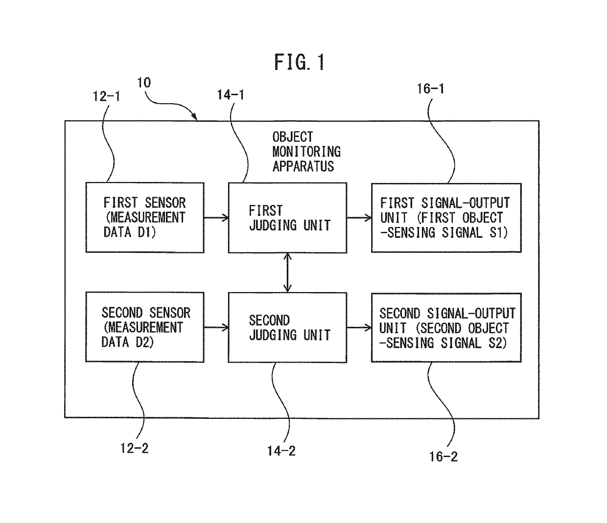
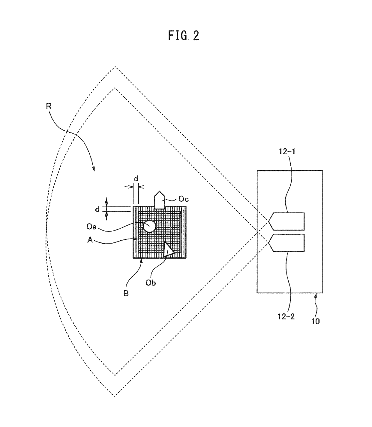
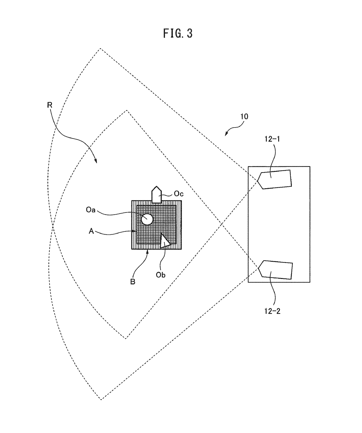
[0026]FIG. 1 illustrates, by functional blocks, a configuration of one embodiment of an object monitoring apparatus 10. FIGS. 2 and 3 schematically illustrate the examples of the spatial arrangement of the object monitoring apparatus 10. The object monitoring apparatus 10 includes a first sensor 12-1 that measures a spatial area R and a second sensor 12-2 that measures a spatial area R corresponding to the spatial area R measured by the first sensor 12-1; a first judging unit 14-1 that judges whether an object (objects Oa, Ob, and Oc in FIGS. 2 and 3; some sort of “material” will be collectively referred to as “object O” hereinafter) is present in a monitored area A defined within the spatial area R, based on measurement data D1 of the first sensor 12-1; a second judging unit 14-2 that jud...


PUM


Abstract

An object monitoring apparatus including sensors. The apparatus includes first and second sensors that measure mutually corresponding spatial areas; a first judging unit that judges whether an object is present in a predetermined monitored area, based on measurement data of the first sensor; a second judging unit that judges whether an object is present in an extended area extending toward an outside of the monitored area, based on measurement data of the second sensor; a first signal-output unit that outputs a first object-sensing signal, when the first judging unit judges that an object is present in the monitored area; and a second signal-output unit that outputs a second object-sensing signal, when the first judging unit judges that an object is present in the monitored area and in a case where the second judging unit judges that an object is present in the extended area.

Description

RELATED APPLICATIONS[0001]The present application claims priority of Japanese Patent Application No. 2017-208182, filed on Oct. 27, 2017, the disclosure of which is hereby incorporated by reference herein in its entirety.BACKGROUND OF THE INVENTION1. Field of the Invention[0002]The present invention relates to an object monitoring apparatus including a plurality of sensors.2. Description of the Related Art[0003]An object monitoring apparatus that monitors an object present in a spatial area by using a sensor for measuring the spatial area is known. Japanese Unexamined Patent Publication No. 9-257919 (JP H9-257919 A), for example, discloses an area monitoring method and an area monitoring apparatus, which are configured to monitor an object in a desired area by using a spread-spectrum radar device. JP H9-257919 A describes a configuration wherein a plurality of radars monitor respective areas partially different from each other, and a configuration wherein a plurality of radars monit...

Claims


Application Information

Patent Timeline
Patent Type & Authority Patents(United States)
IPC IPC(8): G01B11/28G01B9/02
CPCG01B11/28G01B9/02089G01B9/02041G01B11/002G01C3/18G01C15/00
Inventor NAKAMURA, MINORUWATANABE, ATSUSHITAKAHASHI, YUUKI
Owner FANUC LTD
Why Eureka
Try Eureka