Eureka AIR delivers breakthrough ideas for toughest innovation challenges, trusted by R&D personnel around the world.

Container and method of manufacturing the same

a technology of container and container body, which is applied in the field of container, can solve the problems of significant stress on container walls, additional limitations on containers, and difficulty in ensuring the safety of containers, and achieve the effect of similar crush-resistant properties

Active Publication Date: 2019-08-20
ALTIUM PACKAGING LP +1
View PDF40 Cites 14 Cited by
  • Summary
  • Abstract
  • Description
  • Claims
  • Application Information

AI Technical Summary

Benefits of technology

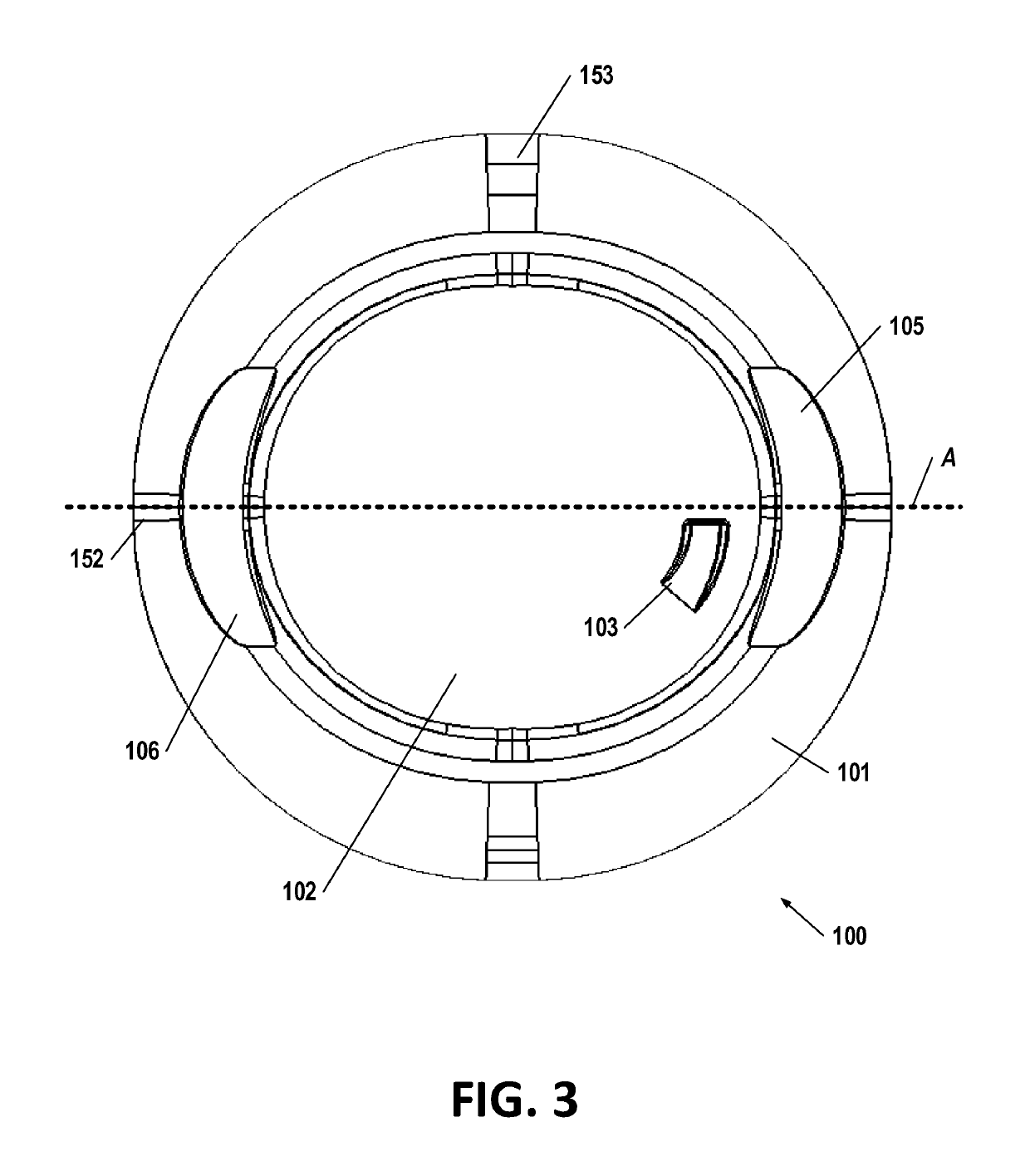
[0004]Certain embodiments are directed to high-strength blow-molded containers having a thin overall sidewall thickness. The container may be particularly suitable for storing and transporting industrial fluids, such as solvents, cleaners, automotive fluids, and / or the like. The container may have a multi-angle top portion configured to distribute vertical compression loads received by the container over a large surface area of the container sidewalls to avoid common crush-failure points surrounding the spout. Moreover, the container includes an integrated handle having similar crush-resistant properties through the introduction of gradual, large radius curves between the handle and adjacent portions of the container, and via the placement of the handle portion outside of the circumference of the spout, such that vertical crushing loads do not create a large localized crushing stress on the bottom proximate a perimeter of the container portion.

Problems solved by technology

Containers that may be used to enclose and transport fluids are often subject to significant stresses during use.
However, containers may be subject to additional limitations, such as a requirement to minimize the cost of materials in the containers, the weight of materials in the containers, and / or the like.
Accordingly, container configurations often are subject to generally conflicting design considerations of maximizing the strength of the container while minimizing the cost and / or weight of materials in the container.

Method used


Image

  • Container and method of manufacturing the same
  • Container and method of manufacturing the same
  • Container and method of manufacturing the same

Examples


Embodiment Construction

[0014]The present invention will now be described more fully hereinafter with reference to the accompanying drawings, in which some, but not all embodiments of the invention are shown. Indeed, the invention may be embodied in many different forms and should not be construed as limited to the embodiments set forth herein. Rather, these embodiments are provided so that this disclosure will satisfy applicable legal requirements. Like numbers refer to like elements throughout.

Overview

[0015]Described herein is a container configured to enclose a fluid and / or other substance. The container comprises a plurality of strengthening features that provide desirable strength characteristics while minimizing the required amount of material necessary to construct the container having the desired strength characteristics. For example, various strengthening features may extend across planar surfaces, curved surfaces, and / or complex curved surfaces in order to provide crush resistance, tensile streng...


PUM


Abstract

A container may comprise a spout, a base portion, and an ovular sidewall extending away from the base portion to the spout. The ovular sidewall comprises a vertical portion, a top transition region, and a top region extending from the top transition region to the spout. The top region comprises at least two discrete linear sections having different slopes between the top transition region and the spout. Moreover, the base portion of the container defines a support surface on which the container rests, a base channel extending across the diameter of the container, and an inset concave panel aligned with a center of the container. The container additionally comprises a handle portion defining a complex-curved face surface interrupting the top transition region and the top region, and a handle extending from a bottom portion of the face surface to a top portion of the face surface.

Description

BACKGROUND[0001]Containers that may be used to enclose and transport fluids are often subject to significant stresses during use. Such containers may be dropped while full or partially full of fluid, stacked on top of one another, supported in a suspended configuration (e.g., when held by a user), and / or the like. Accordingly, various containers incorporate strengthening features in order to provide strength to the container against breakage.[0002]However, containers may be subject to additional limitations, such as a requirement to minimize the cost of materials in the containers, the weight of materials in the containers, and / or the like. Accordingly, container configurations often are subject to generally conflicting design considerations of maximizing the strength of the container while minimizing the cost and / or weight of materials in the container.[0003]Accordingly, a need exists for containers providing an optimal balance of maximum strength against undesired breakage while m...

Claims


Application Information

Patent Timeline
Patent Type & Authority Patents(United States)
IPC IPC(8): B65D23/10B65D47/12B65D1/02
CPCB65D1/0261B65D47/122B65D23/10B65D2501/0081B65D1/0223B65D1/0284
Inventor PALMER, JOEYJANECZEK, JAMES
Owner ALTIUM PACKAGING LP
Why Eureka
Eureka Blog
Learn More