
Hybrid scanning display and associated mechanisms

Active Publication Date: 2019-08-13
PARCELS BRADLEY JAMES
View PDF2 Cites 1 Cited by
  • Summary
  • Abstract
  • Description
  • Claims
  • Application Information

AI Technical Summary

Benefits of technology

This patent is about a new display technology that can improve upon existing scanned display technology. The technology can create low-cost displays that can replace computer monitors and televisions. It can also make displays on mobile devices folding and allow users to walk around virtual objects. Additionally, it can provide fully immersive simulation environments with visual fidelity. The technology also aims to fix issues with existing displays, such as shortcomings.

Problems solved by technology

Despite increasing in ubiquity, current display technologies remain quite limited by many factors: size, resolution, viewing angle, and of course—cost.
Traditional televisions and computer monitors are rapidly growing in both size and resolution, while simultaneously shrinking in depth and weight—but despite the impressive rate of advancement—users remain confronted by competing priorities: a larger display with more resolution is almost always desirable—but the physical space occupied by such a display can often be limiting, as can the cost—both of which increase proportionately with the desirable traits.
Head Mounted Displays (HMDs) have long been heralded as the panacea for these, and many other display shortcomings—however—HMDs have failed to deliver on this promise to date.
Available HMDs are plagued by low resolution, poor image quality, severe user discomfort, and very high cost.
Recent work from Oculus, Valve, Google, and Sony (among others) has come a long way towards improving on many of these individual shortcomings; but unfortunately, even the best HMDs today do not solve the full group of issues mentioned.
As a result, HMDs are not currently practical for anything but niche and novelty use.
The fact that no commercially available HMD is comfortable and inconspicuous enough for use in everyday life is high on the list of remaining problems.
Google “Glass” was getting closer in this regard—but they have only proven the overall point—the (now discontinued) product offered a resolution of only 640×360 at a price that was difficult to justify, when many mainstream smartphones now include displays with 2560×1600 resolutions.
The OculusRift” went the other way—their displays are improving in resolution (1080×1200 per eye), and pricing is significantly lower than the Google “Glass” was—however, this device is bulky and obtrusive; condemning it's use to gaming and niche applications.
It was a good start, but still required bulky optics and specialized micro-arrays of LEDs.
Building on these ideas, in U.S. Pat. No. 5,764,280 (filed ten years later—in 1997), Bloom et al. appear to have made another leap forward by bringing the array of light sources outside of the headset; but unfortunately, this meant giving up the possibility of an immersive system.
Furthermore—I have found serious flaw with the display of said patent: the user must keep their head perfectly perpendicular to the array, or the image is distorted into a parallelogram—devolving completely to a line when at 90 degrees.
Bloom et al. failed to identify or address this issue, and as a result, their architecture remains entirely unsuitable for many important applications.

Method used


Image

  • Hybrid scanning display and associated mechanisms
  • Hybrid scanning display and associated mechanisms
  • Hybrid scanning display and associated mechanisms

Examples


first embodiment

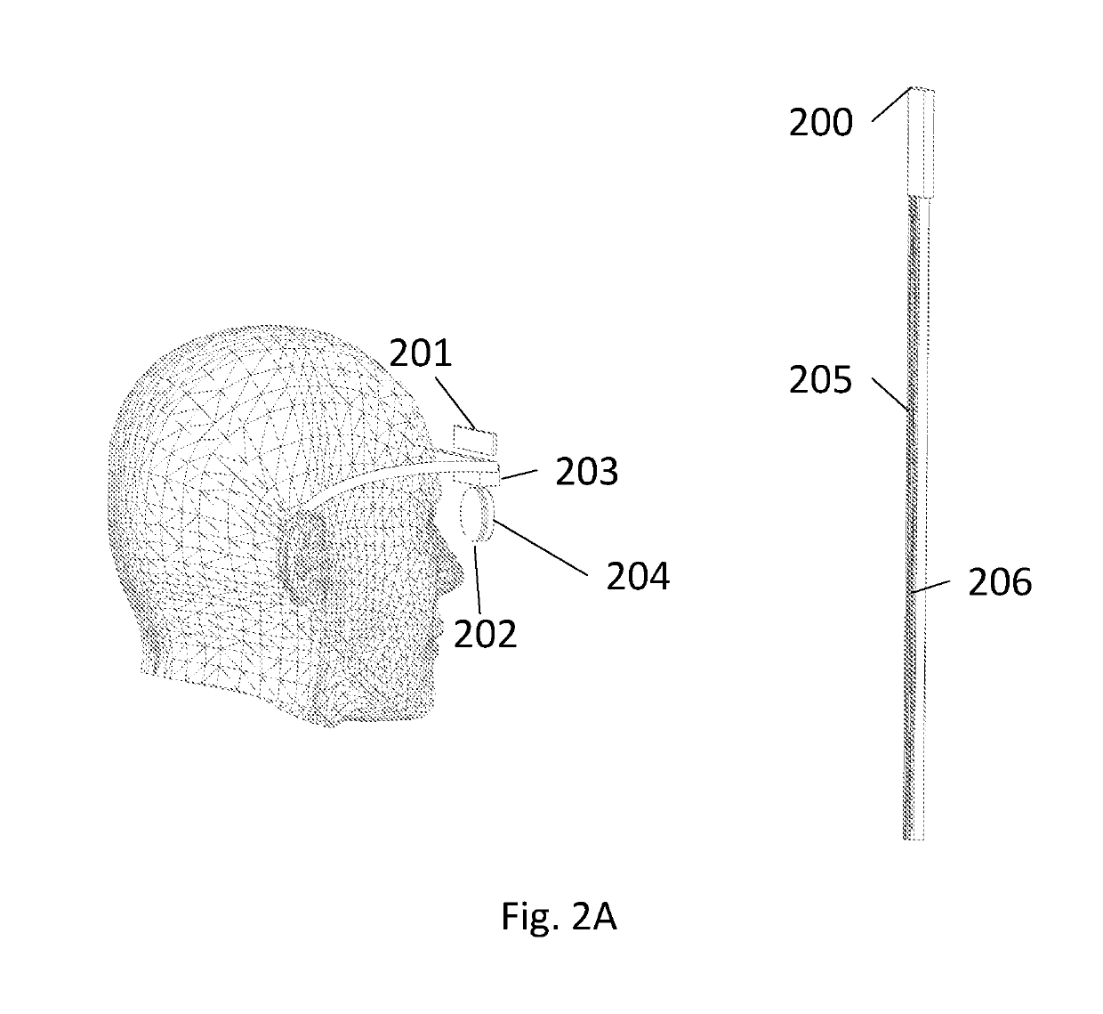
[0020]FIG. 2A—First embodiment

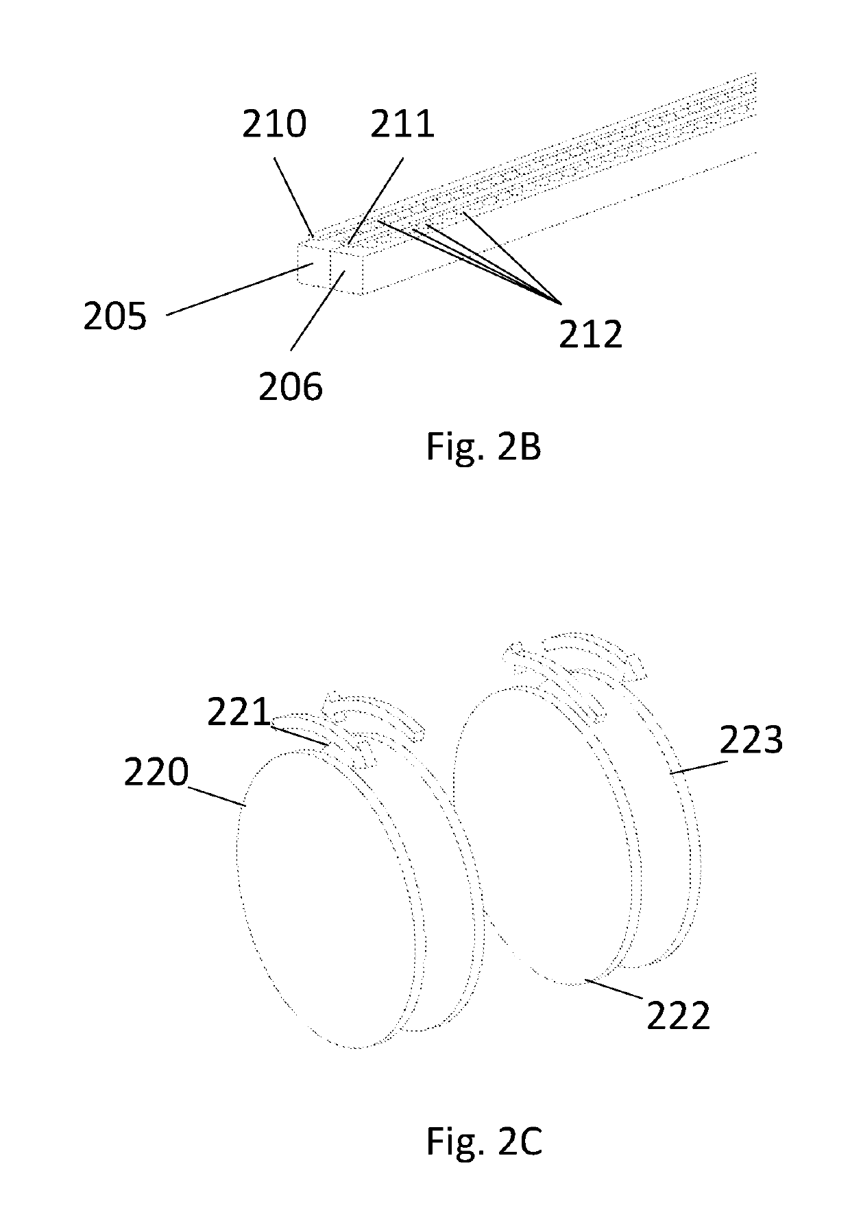
[0021]FIG. 2B—Close-up of dual array

[0022]FIG. 2C—Dual Risley scanner

[0023]FIG. 2D—Display from an angle showing perspective effect

[0024]FIG. 2E—View from one angle

[0025]FIG. 2F—View from a second angle

second embodiment

[0026]FIG. 3—Second embodiment

[0027]FIG. 4—Steerable array

[0028]FIG. 5—2D offset lens or holographic lens

[0029]FIG. 6—1D scanner using servo to act as 2D scanner

[0030]FIG. 7—2D scanner made up of two 1D scanners

DETAILED DESCRIPTION

[0031]As much of the operation and physical structure of several embodiments are shared with the work of Bloom et al., we incorporate by reference their U.S. Pat. No. 5,764,280 (issued Jun. 9, 1998) in it's entirety, in an effort to maintain a clear and compact disclosure.

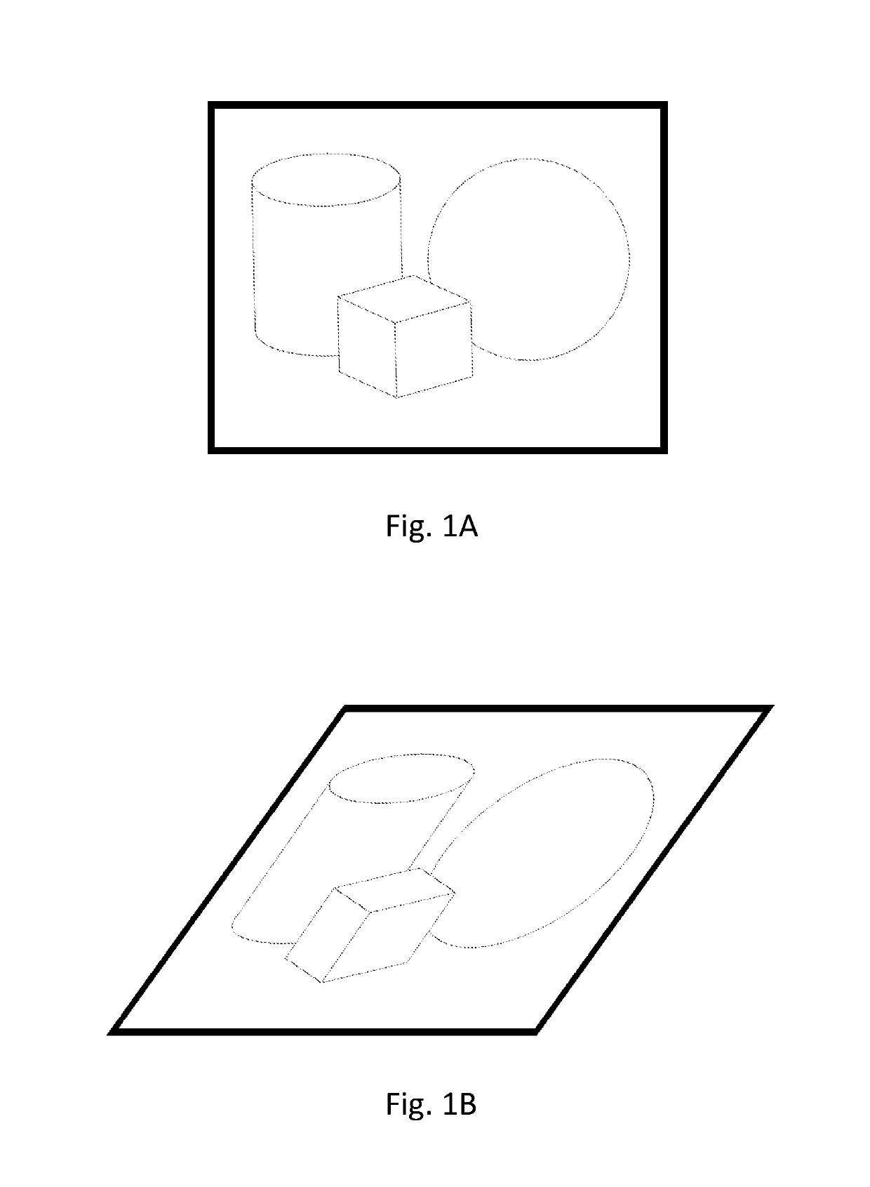
[0032]We will first address a serious flaw that I have found in displays built according to U.S. Pat. No. 5,764,280; which is that if a user's head is not perfectly perpendicular to the light source array of such a display, the perceived two-dimensional image becomes severely distorted—progressing down to a single line of light when the vertical axis of the user's head is parallel to the axis of the linear light source array. This effect is illustrated by observing FIG. 1A, which displays...


PUM


Abstract

A display device that significantly improves upon existing scanned display technology (Bloom et al. U.S. Pat. No. 5,764,280), and allows for entirely new display form factors. Just a few of the embodiments may provide: low cost displays that replace computer monitors and televisions, folding displays on mobile devices, entirely new forms such as pedestal / conference room displays that allow a user to walk around virtual objects, or even provide fully immersive simulation environments with visual fidelity never before possible. Furthermore, one or more embodiments eliminate the shortcomings, discovered by the present inventor, in displays of the type described by U.S. Pat. No. 5,764,280.

Description

CROSS-REFERENCE TO RELATED APPLICATIONS[0001]This application claims the benefit of provisional patent application Ser. No. 62 / 215,698, filed 2015 Sep. 8 by the present inventor, which is incorporated by reference.BACKGROUNDPrior Art[0002]The following is a tabulation of some prior art that presently appears relevant:[0003]U.S. PatentsPat. No.Kind CodeIssue DatePatentee5,764,280Jun. 9, 1998Bloom4,934,773Jun. 19, 1990Becker[0004]U.S. patent application PublicationsPublication Nr.Kind CodePubl. DateApplicantUS20160131761A1May 12, 2016YatesNONPATENT LITERATURE DOCUMENTS[0005]Escuti, M. J., Optica journal Vol. 2 No. 11, November 2015, “Fabrication of ideal geometric-phase holograms with arbitrary wavefronts[0006]Escuti, M. J., IEEE Photonics Technology Letters Vol. 22 No. 4, February 2015, “High-Throughput Continuous Beam Steering Using Rotating Polarization Gratings”BACKGROUND ART[0007]Despite increasing in ubiquity, current display technologies remain quite limited by many factors: si...

Claims


Application Information

Patent Timeline
IPC IPC(8): G02B26/10G09G3/00G09G3/02G02B27/28G02B27/00G02B27/01G02B26/08
CPCG09G3/02G09G3/002G02B26/101G02B27/288G02B27/0172G02B27/0093G09G2340/0407G02B2027/0147G09G2320/08G09G2320/028G02B2027/011G02B2027/0127G02B26/106G02B30/25G02B2027/0134G02B2027/0174
Inventor PARCELS, BRADLEY JAMES
Owner PARCELS BRADLEY JAMES
Learn More