
Motor mounting device

a technology for mounting devices and motors, which is applied to liquid fuel engines, machines/engines, mechanical equipment, etc., can solve the problems of high production cost, annoying occupants, and complicated production, and achieve the effect of cost-effective manufacturing and simple structur

Inactive Publication Date: 2019-08-06
MAHLE INT GMBH
View PDF21 Cites 3 Cited by
  • Summary
  • Abstract
  • Description
  • Claims
  • Application Information

AI Technical Summary

Benefits of technology

[0009]It is therefore an object of the invention to provide a motor mounting device which is simple in structure and still cost-effective to manufacture.
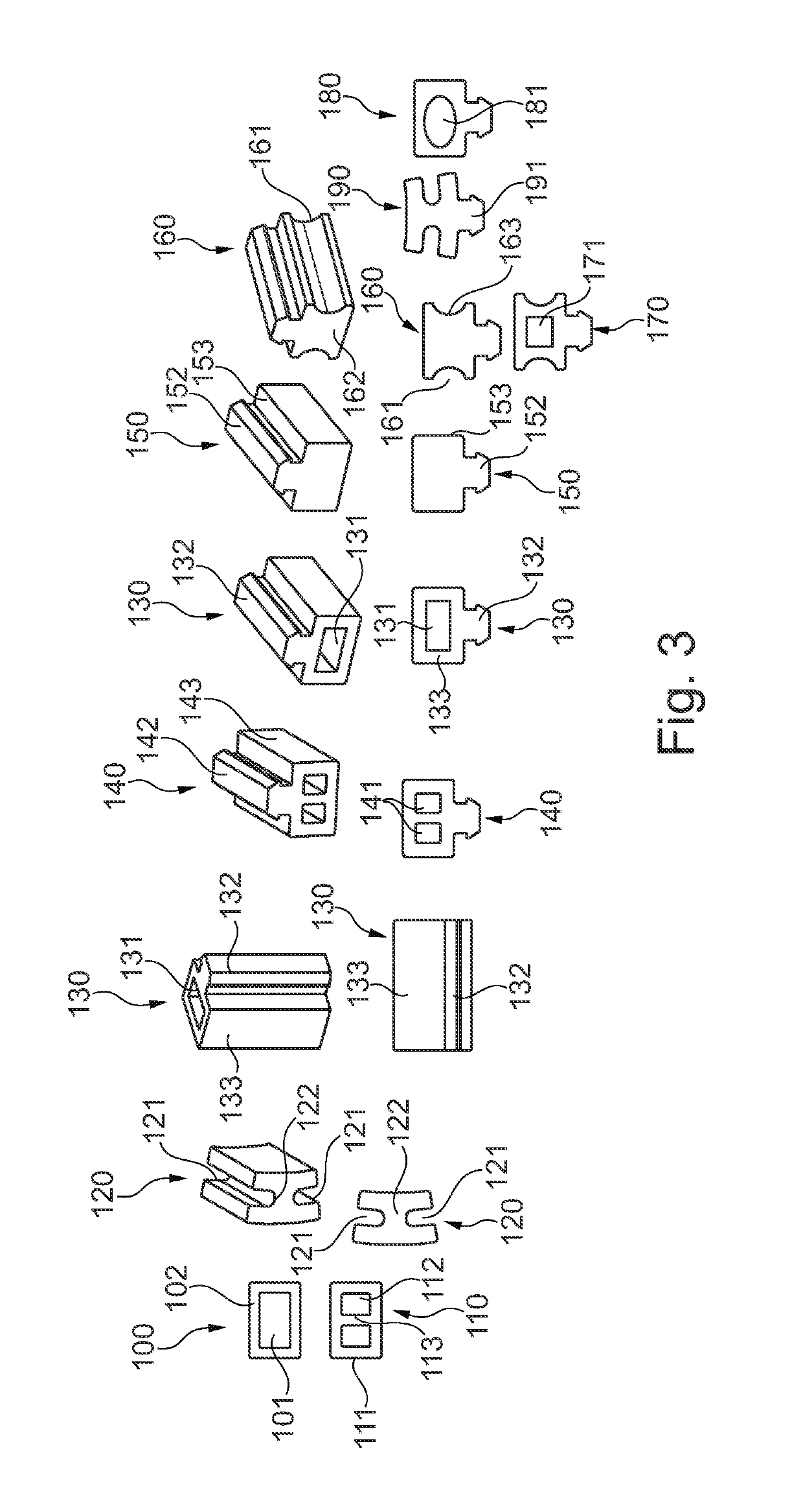
[0010]An exemplary embodiment of the invention relates to a motor mounting device having a motor adapter, which is formed substantially ring-shaped or pot-shaped and is used to receive a housing of an electric motor, and having a motor mount, which is used to hold the motor adapter, whereby elastic damping elements are disposed between the motor adapter and the motor mount, characterized in that the damping elements are formed as extruded profiles. As a result, the damping element can be produced cost-effectively and trimmed to the required length, so that it can be produced as a type of kit and can also be used in different application examples.
[0013]The damping elements can be disposed at an angular distance of 60° and / or 120° to one another. As a result, the damping elements can be disposed advantageously at vibration nodes in order to achieve effective damping.
[0014]At least two of the damping elements or the damping elements can be disposed substantially at a same axial height and / or that at least individual damping elements are disposed offset to one another in the axial direction. Their action is especially effective as a result, because the amplitude of the vibration can be dampened especially well.
[0015]The damping elements can be disposed substantially at the axial height of the center of gravity of the electric motor. Their action is especially effective as a result, because the amplitude of the vibration of the center of gravity can be dampened especially well.

Problems solved by technology

Thus, the blower motor is received in the motor adapter and held in a vibration damping manner against the motor mount, so that vibrations in the region of the blower motor are not transmitted by structure-borne sound to other vehicle parts, a situation that could be perceived as annoying by the occupants.
This is complicated in terms of production which is why damping elements are expensive.
As a result, a complicated production method is also disclosed which is accordingly expensive in terms of production.

Method used


Image

  • Motor mounting device
  • Motor mounting device
  • Motor mounting device

Examples


Embodiment Construction

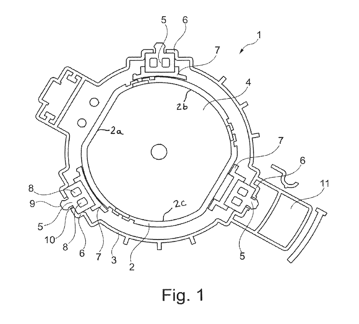
[0043]FIG. 1 in a schematic illustration shows a motor mounting device 1 in a sectional view. Motor mounting device 1 has a motor adapter 2 for receiving and holding a motor 4, such as particularly a blower motor of a ventilation, heating, or air conditioning unit. The motor in this case is made as an electric motor and is used in particular to produce an air stream. Motor adapter 2 is advantageously made ring-shaped or pot-shaped and surrounds the housing of motor 4 in this exemplary embodiment, for example, with three fingers 2a, 2b, 2c only partially or incompletely or alternatively also completely. A motor mount 3 is provided, furthermore, which surrounds motor adapter 2 substantially completely and which can be fastened, for example, on the vehicle side.

[0044]Motor mount 3 is used to hold motor adapter 2 received in it. Elastic damping elements 5 are disposed between motor adapter 2 and motor mount 3 for vibration decoupling. These are formed as an extruded profile for better m...


PUM


Abstract

A motor mounting device having a motor adapter that is formed substantially ring-shaped or pot-shaped and is used to receive a motor, and having a motor mount, which is used to hold the motor adapter, whereby elastic damping elements are disposed between the motor adapter and the motor mount, whereby the damping elements are formed as extruded profiles.

Description

[0001]This nonprovisional application claims priority under 35 U.S.C. § 119(a) to German Patent Application No. 10 2014 224 926.0, which was filed in Germany on Dec. 4, 2014, and which is herein incorporated by reference.BACKGROUND OF THE INVENTION[0002]Field of the Invention[0003]The invention relates to a motor mounting device, particularly for a blower motor of a ventilation, heating, or air conditioning unit of a motor vehicle.[0004]Description of the Background Art[0005]Motor mounting devices are used to hold a blower motor and to support it elastically. A motor adapter is provided for this purpose, which surrounds the housing of the electric motor substantially in the shape of a pot and thus holds the blower motor. A motor mount is provided, furthermore, which holds the blower motor with the motor adapter, whereby damping elements, which dampen vibrations, are disposed between the motor adapter and the motor mount. Thus, the blower motor is received in the motor adapter and he...

Claims


Application Information

Patent Timeline
Patent Type & Authority Patents(United States)
IPC IPC(8): H02K5/24F04D25/06F04D25/08F04D29/66
CPCH02K5/24F04D29/668F04D25/08F04D25/06F02B77/00F16F15/04
Inventor WOLF, WALTER
Owner MAHLE INT GMBH
Learn More