Turbine engine and method of cooling thereof
a technology of turbine engines and cooling methods, applied in the field of turbine engines, can solve the problems of reducing the service life of electrical and electronic components in the undercowl space, and being particularly sensitiv
- Summary
- Abstract
- Description
- Claims
- Application Information
AI Technical Summary
Benefits of technology
Problems solved by technology
Method used
Image
Examples
first embodiment
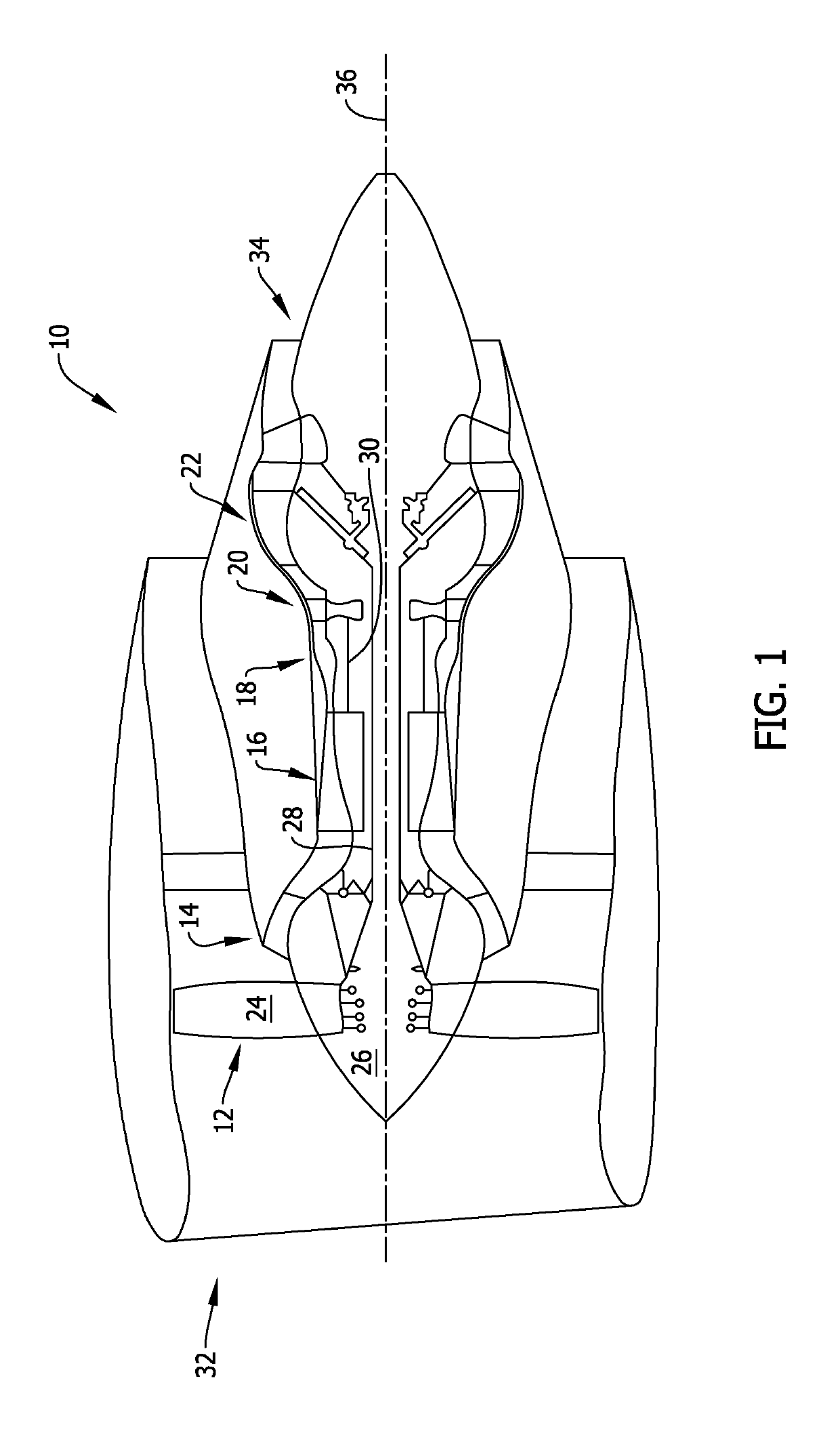
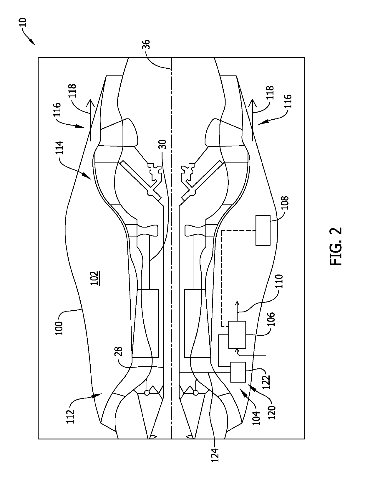
[0022]FIG. 2 is a schematic illustration of a portion of turbine engine 10 (shown in FIG. 1), in accordance with the disclosure. In the exemplary embodiment, turbine engine 10 further includes a core engine cowl 100 having a hollow compartment 102 that houses one or more mechanical or electronic components therein. For example, in one embodiment, a cooling system 104 is positioned within hollow compartment 102. Cooling system 104 includes a cooling airflow source, such as at least one cooling fan 106 positioned within hollow compartment 102, and a full authority digital engine control (FADEC) system 108 coupled in communication with cooling fan 106. FADEC system 108 is coupled, either by wired or wirelessly connectivity, in communication with one or more subsystems or components of turbine engine 10 and cooling system 104 to control the operation of turbine engine 10 and cooling system 104 at a predetermined stage of operation of turbine engine 10, as will be explained in more detai...
second embodiment
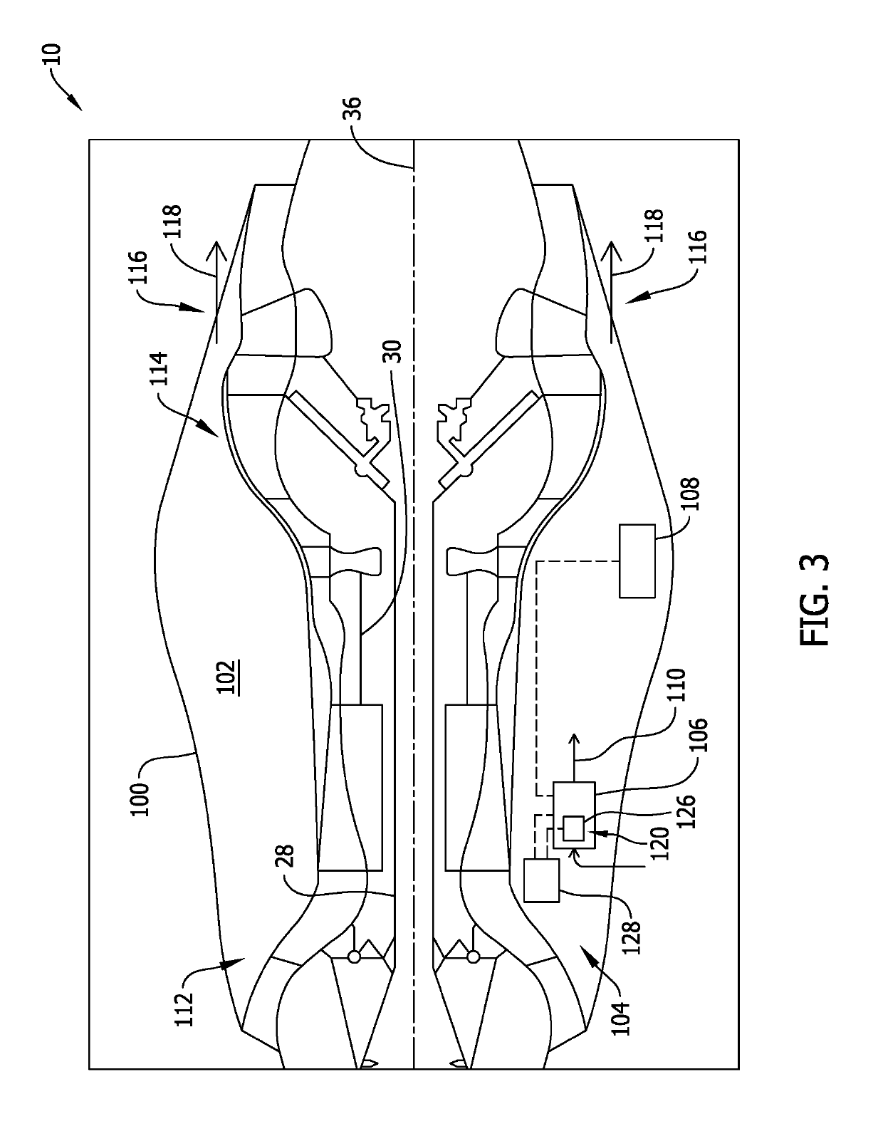
[0027]FIG. 3 is a schematic illustration of a portion of turbine engine 10 (shown in FIG. 1), in accordance with the disclosure. In the exemplary embodiment, as described above, cooling fan 106 is configured to operate for a preset time after turbine engine 10 has been shut down. For example, cooling fan 106 includes timer device 120 that shuts down cooling fan 106 at a time after actuation of cooling fan 106. In one embodiment, timer device 120 is an electronic timer 126 having an independent power supply 128. Independent power supply 128 enables electronic timer 126 to operate independent of FADEC system control. In some embodiments, independent power supply 128 also powers cooling fan 106 such that cooling fan 106 is operable after turbine engine shutdown.
third embodiment
[0028]FIG. 4 is a schematic illustration of a portion of turbine engine 10 (shown in FIG. 1), in accordance with the disclosure. In the exemplary embodiment, cooling system 104 further includes an airflow conduit 130 extending from cooling fan 106. More specifically, airflow conduit 130 includes an inlet 132 and a discharge outlet 134. Airflow conduit 130 is oriented such that cooling airflow 110 is received at inlet 132, channeled through airflow conduit 130, and discharged towards predetermined high temperature regions within core engine cowl 100. For example, as described above, hollow compartment 102 houses one or more electronic components therein, such as FADEC system 108. As such, in the exemplary embodiment, discharge outlet 134 is positioned such that cooling airflow 110 is channeled towards FADEC system 108 in a more efficient and direct manner. In an alternative embodiment, only a portion of cooling airflow 110 discharged from cooling fan 106 is channeled through airflow ...
PUM
 Abstract
Description
Claims
Application Information
 - R&D
- Intellectual Property
- Life Sciences
- Materials
- Tech Scout
- Unparalleled Data Quality
- Higher Quality Content
- 60% Fewer Hallucinations
Browse by: Latest US Patents, China's latest patents, Technical Efficacy Thesaurus, Application Domain, Technology Topic, Popular Technical Reports.
© 2025 PatSnap. All rights reserved.Legal|Privacy policy|Modern Slavery Act Transparency Statement|Sitemap|About US| Contact US: help@patsnap.com


