Touch sensor unit
a technology of touch sensor and sensor body, which is applied in the field of touch sensor units, can solve the problems of complex terminal treatment, increase of components, and increase in cost, and achieve the effects of simplifying terminal treatment, and reducing the insertion load of conductive components
- Summary
- Abstract
- Description
- Claims
- Application Information
AI Technical Summary
Benefits of technology
Problems solved by technology
Method used
Image
Examples
embodiment 1
[0033 of the disclosure is described in detail below with reference to the drawings.
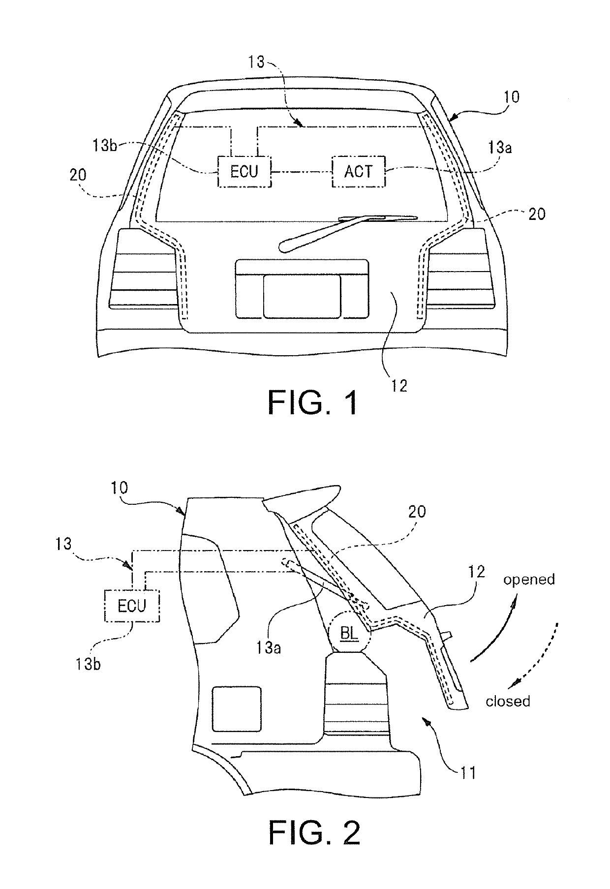
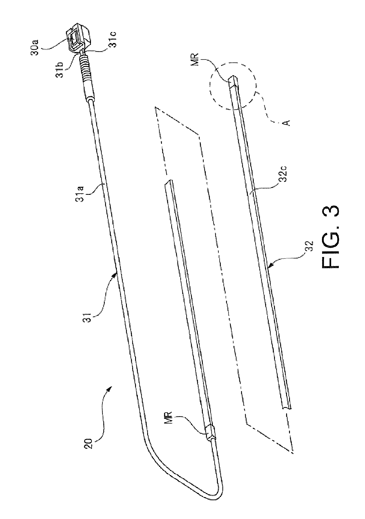
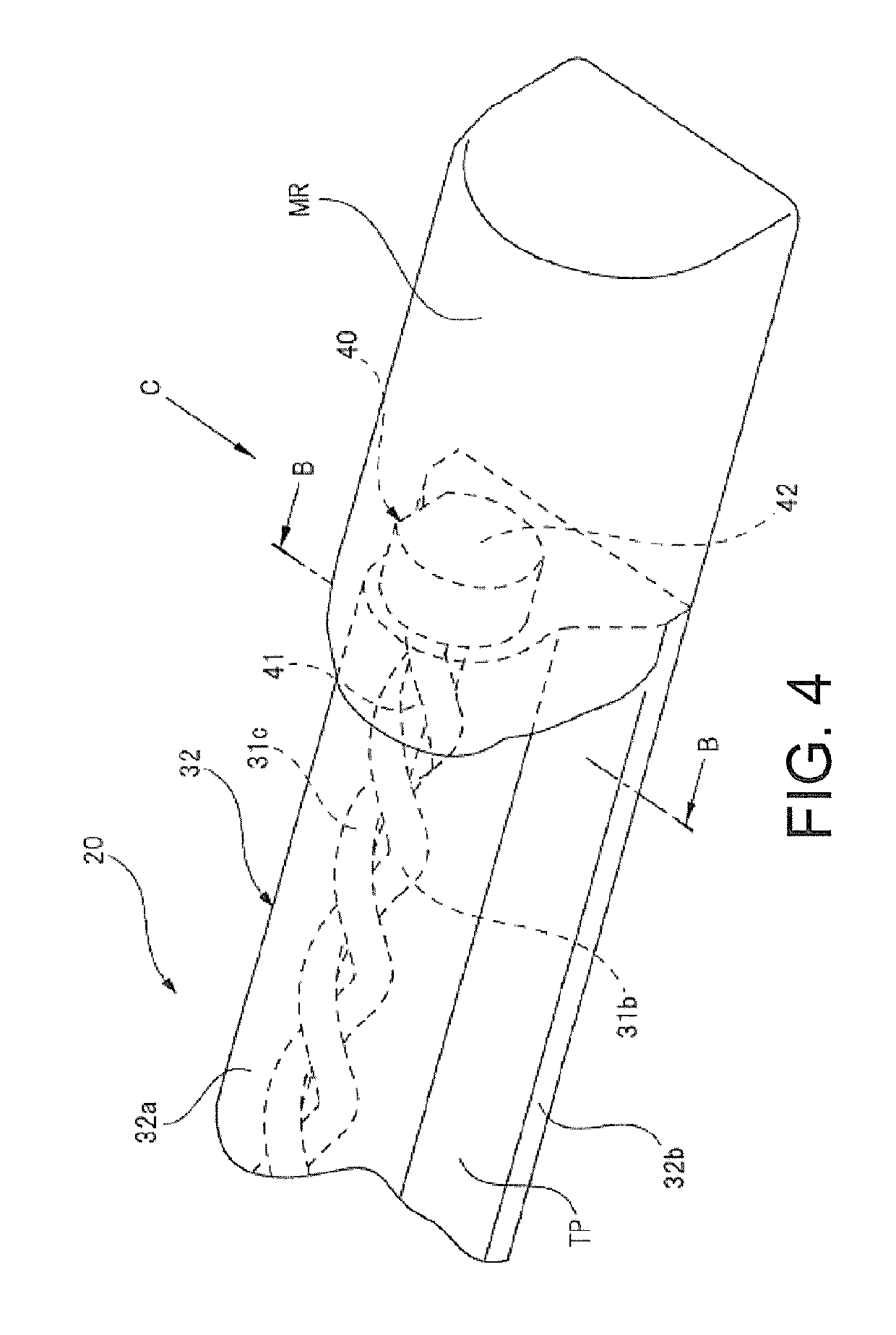
[0034]FIG. 1 is a front view of a tailgate equipped with a touch sensor unit. FIG. 2 is a side view obtained by observing laterally from a rear side of a vehicle in FIG. 1. FIG. 3 is a perspective view showing the touch sensor unit. FIG. 4 is an enlarged view of a dashed circle A section in FIG. 3. FIG. 5 is a sectional view along a B-B line in FIG. 4. FIG. 6 is an illustrative drawing illustrating a spiral state of a pair of electrodes observed from a direction of arrow C in FIG. 4. FIG. 7 is a perspective view showing a conductive component of embodiment 1. FIG. 8A and FIG. 8B are illustrative drawings illustrating a terminal treatment of the touch sensor unit. FIG. 9 is a graph obtained by comparing a dispersion situation of resistance value in the prior art and a dispersion situation of resistance value in the disclosure.
[0035]A vehicle 10 shown in FIG. 1 and FIG. 2 is a so-called hatchback vehic...
embodiment 2
[0085]FIG. 10 is a perspective view showing a conductive component of the
[0086]The only difference of a conductive component 50 of the embodiment 2 is the shape of a body section 51. More specifically, the cross section of the body section 51 along a direction across the longitudinal direction is approximately equilateral triangle-shaped. And on the outer circumference section of the body section 51, three convex sections 51a extending along the longitudinal direction of the body section 51 are arranged. These convex sections 51a are arranged across the whole area of the body section 51 in the longitudinal direction, and sink into the electrodes 31b and 31c in the state of being inserted into the space between the electrodes 31b and 31c (see FIG. 5) inside the insulating tube 31a. Besides, the three convex sections 51a are disposed with equal intervals (an interval of 120°) along the circumferential direction of the body section 51.
[0087]In the embodiment 2 formed in this way, the s...
embodiment 3
[0089]FIG. 11 is a perspective view showing a conductive component of the
[0090]The only difference of a conductive component 60 of the embodiment 3 is the shape of a body section 61. More specifically, the cross section of the body section 61 along a direction across the longitudinal direction is approximately regular hexagon-shaped. And on the outer circumference section of the body section 61, six convex sections 61a extending along the longitudinal direction of the body section 61 are arranged. These convex sections 61a are arranged across the whole area of the body section 61 in the longitudinal direction, and sink into the electrodes 31b and 31c in the state of being inserted into the space between the electrodes 31b and 31c (see FIG. 5) inside the insulating tube 31a. Besides, the six convex sections 61a are disposed with equal intervals (an interval of 60°) along the circumferential direction of the body section 61.
[0091]In the embodiment 3 formed in this way, the same effect...
PUM
 Abstract
Description
Claims
Application Information
 - R&D
- Intellectual Property
- Life Sciences
- Materials
- Tech Scout
- Unparalleled Data Quality
- Higher Quality Content
- 60% Fewer Hallucinations
Browse by: Latest US Patents, China's latest patents, Technical Efficacy Thesaurus, Application Domain, Technology Topic, Popular Technical Reports.
© 2025 PatSnap. All rights reserved.Legal|Privacy policy|Modern Slavery Act Transparency Statement|Sitemap|About US| Contact US: help@patsnap.com


