
Grout installation apparatus

a technology of installation apparatus and grout, which is applied in the field of grout, can solve the problems of labor-intensive and time-consuming procedures, difficult to remove excess grout from the surface of tiles, and inflexible grout, etc., and achieve the effect of efficient pushing grout into spaces

Active Publication Date: 2019-07-30
BONACHEA RUIZ RUDY AMMED
View PDF13 Cites 9 Cited by
  • Summary
  • Abstract
  • Description
  • Claims
  • Application Information

AI Technical Summary

Benefits of technology

This patent is about an apparatus for installing and removing grout on tiled surfaces. It includes a grout tank and a grout dispensing head for efficient application of grout between tiles. The apparatus also has a piston for pushing the grout from the tank to the dispensing head, and a rear squeegee for removing excess grout from the surface. The technical effect is improved efficiency and precision in grout installation and removal.

Problems solved by technology

Grout is not flexible, and cannot expand and contract with changing temperatures.
Excess grout must be removed as soon as application thereof is completed, as it is very difficult to remove excess grout from the surface of the tiles once it has cured.
The most common procedure used to remove such excess grout from the surface of the tiles is to manually sponge off the excess material with a wet sponge; a procedure which is labor intensive and time consuming.
However, this method has drawbacks.

Method used


Image

  • Grout installation apparatus
  • Grout installation apparatus
  • Grout installation apparatus

Examples


Embodiment Construction

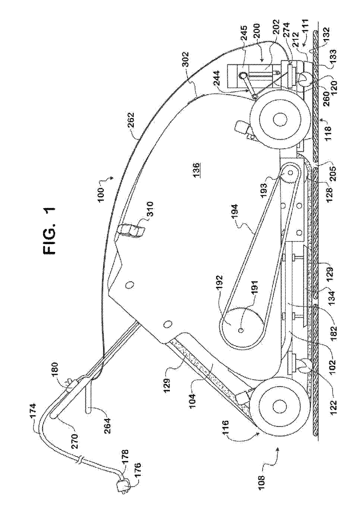
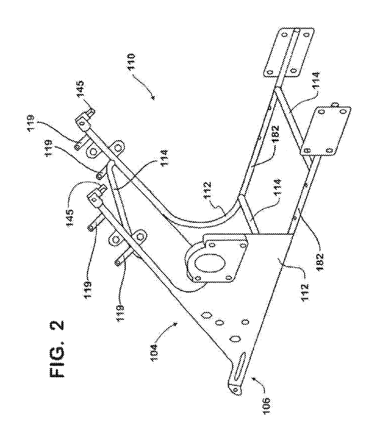
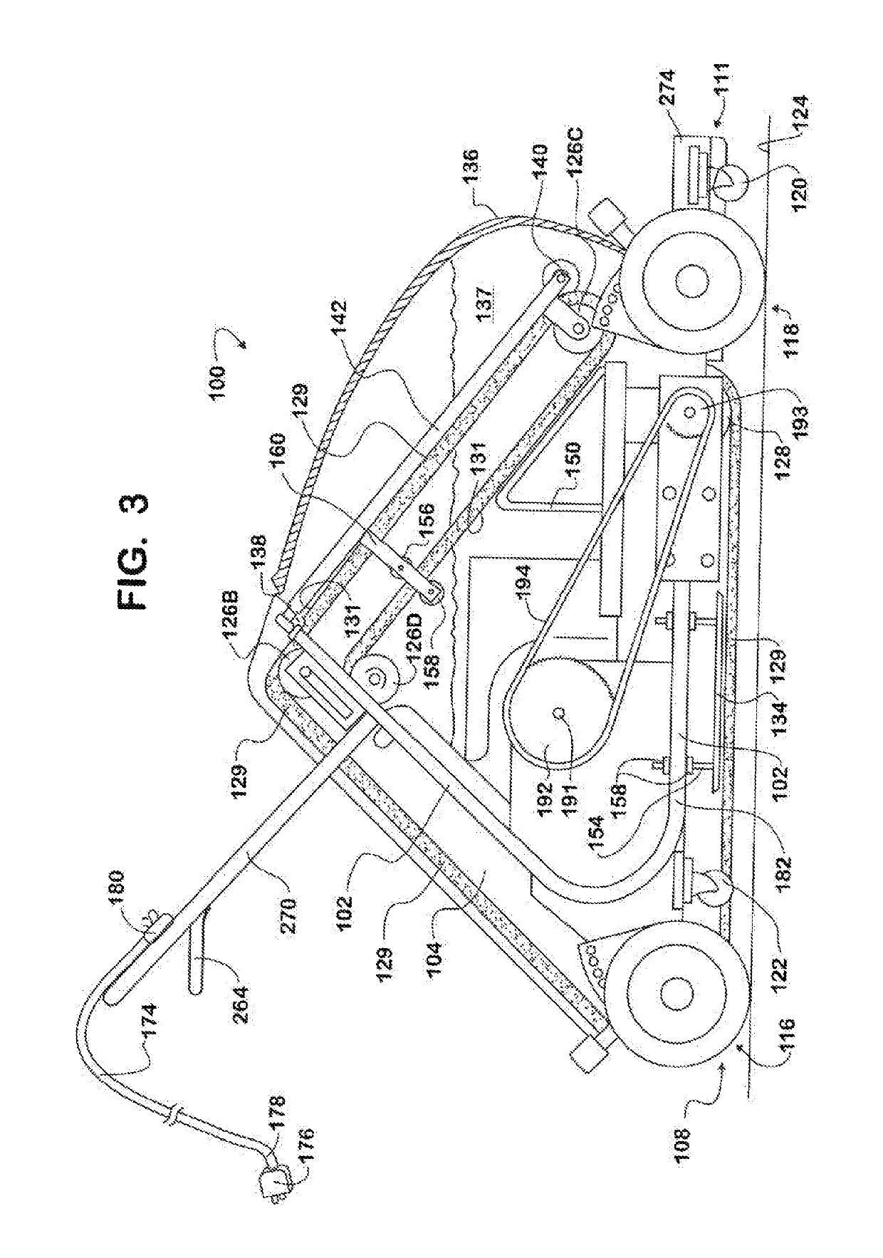
[0033]The following detailed description is merely exemplary in nature and is not intended to limit the described embodiments or the application and uses of the described embodiments. As used herein, the word “exemplary” or “illustrative” means “serving as an example, instance, or illustration.” Any implementation described herein as “exemplary” or “illustrative” is not necessarily to be construed as preferred or advantageous over other implementations. All of the implementations described below are exemplary implementations provided to enable persons skilled in the art to make or use the embodiments of the disclosure and are not intended to limit the scope of the disclosure, which is defined by the claims. For purposes of description herein, the terms “upper”, “lower”, “left”, “rear”, “right”, “front”, “vertical”, “horizontal”, and derivatives thereof shall relate to the invention as oriented in FIG. 1. Furthermore, there is no intention to be bound by any expressed or implied theo...


PUM


Abstract

A grout installation apparatus having a grout applying member and a grout removal member rearward of the grout applying member. The grout applying member includes a grout tank for storing grout, and a grout dispensing head which rests against an area of a tiled surface, confines said area and applies grout to the confined area to efficiently push grout into spaces between tiles. The grout applying member can include a user-operable piston to push the grout from the grout tank to the grout dispensing head. The grout dispensing head can include a rear squeegee for scraping and sweeping excess grout forward from the confined area of the tiled surface. The grout removal member wipes excess grout from the tile surface.

Description

FIELD OF THE INVENTION[0001]The present invention relates generally to an apparatus which applies grout material between tiles and removes excess grout left on the surface of the tiles after application of the grout. More particularly, the invention is directed to a grout installation apparatus and method for using the apparatus to apply grout into spaces between tiles at a speed that is much faster than can be accomplished by manual methods used in the art, with the apparatus also removing any excess grout left on the surface of the tiles after upstream application thereof.BACKGROUND OF THE INVENTION[0002]Tiles are typically held in place by cement, also known as mud, or other suitable adhesives, such as epoxy, mastic, and the like. Grout is a non-adhesive material that is applied between tiles to fill voids between adjacent tiles. Grout typically comprises a mixture of water, cement, sand, and may further include a color tint, and / or fine gravel. It is applied as a thick liquid an...

Claims


Application Information

Patent Timeline
Patent Type & Authority Patents(United States)
IPC IPC(8): B05C11/10E04F21/165
CPCE04F21/1652B05C11/1039E04F21/165
Inventor BONACHEA RUIZ, RUDY AMMED
Owner BONACHEA RUIZ RUDY AMMED
Learn More