
Method and system for verifying panoramic images of implants

a panoramic image and imaging technology, applied in the field of methods and systems for verifying implants, can solve the problems of significant morbidity and/or mortality, large damage at the surgical site,

Active Publication Date: 2019-07-16
REMEX MEDICAL CORP
View PDF20 Cites 0 Cited by
  • Summary
  • Abstract
  • Description
  • Claims
  • Application Information

AI Technical Summary

Benefits of technology

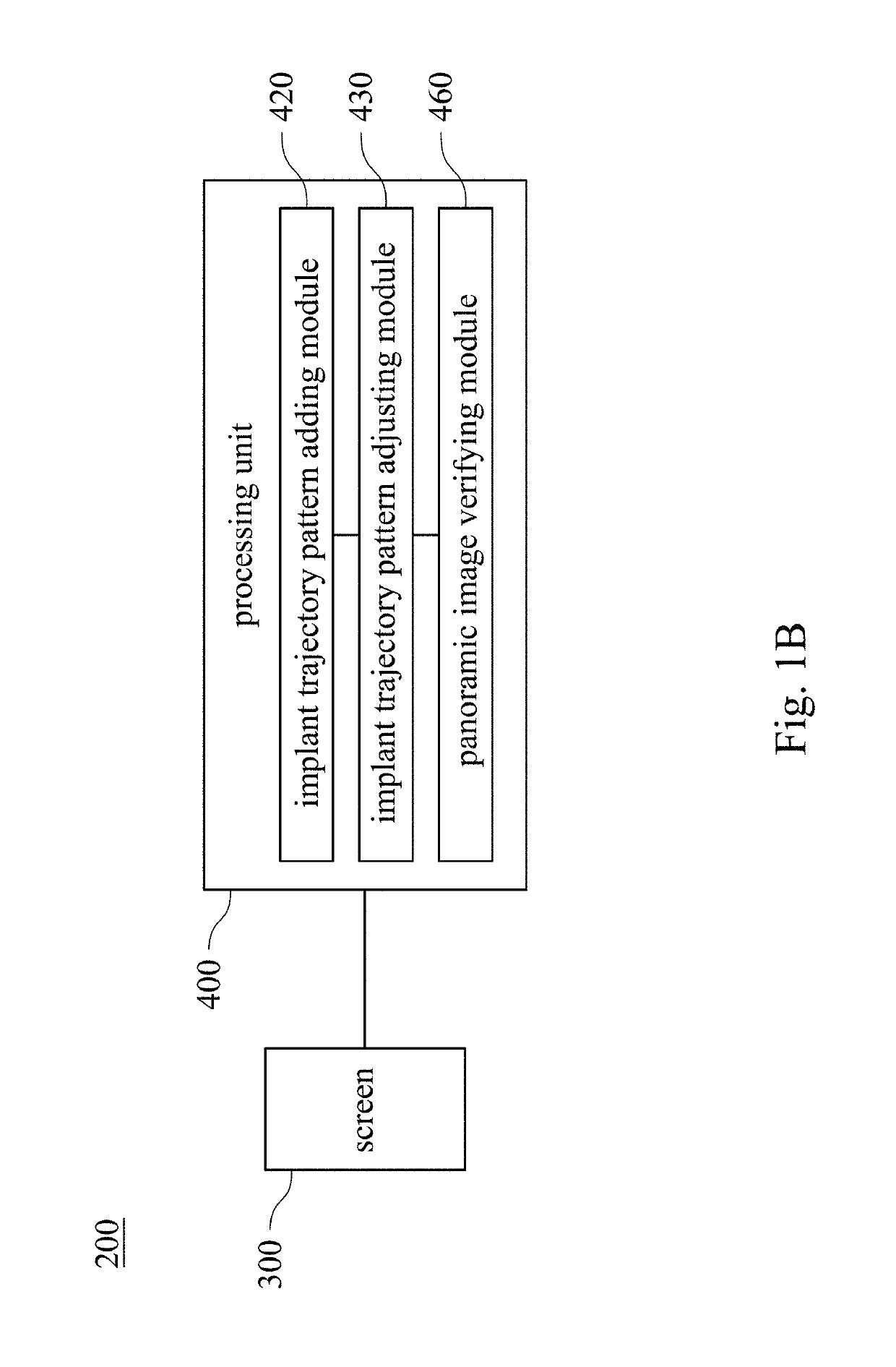
The present invention provides a method and system for verifying panoramic images of implants and checking the relative position between an implant trajectory pattern and a surgical site pattern. This helps in accurately determining the placement of the implant and ensuring its stability during the recovery period. The method and system include a pre-planning interface for displaying the surgical site pattern and the implant trajectory pattern, an implant trajectory pattern adding step, an implant trajectory pattern adjusting step, and a panoramic image verifying step. The system includes a screen and a processing unit with an implant trajectory pattern adding module, an implant trajectory pattern adjusting module, and a panoramic image verifying module. The panoramic image verifying module rotates the surgical site pattern around the implant trajectory pattern at a viewing angle and ensures a clear view of the implant. The technical effect of the present invention is to provide a reliable and accurate tool for verifying spinal implant trajectories and ensuring their proper positioning during surgery.

Problems solved by technology

If there is a slight error in the surgical operation, it may cause huge damage at a surgical site.
However, adjacent to the spine are numerous vital structures and organs, in particular the cervical and thoracic spine regions, which have very low tolerance for surgically created injuries that may ultimately lead to significant morbidity and / or mortality.

Method used


Image

  • Method and system for verifying panoramic images of implants
  • Method and system for verifying panoramic images of implants
  • Method and system for verifying panoramic images of implants

Examples


Embodiment Construction

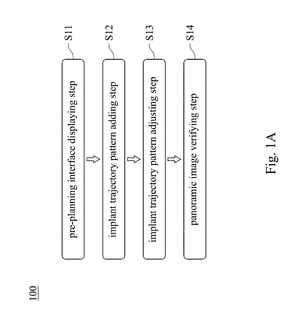
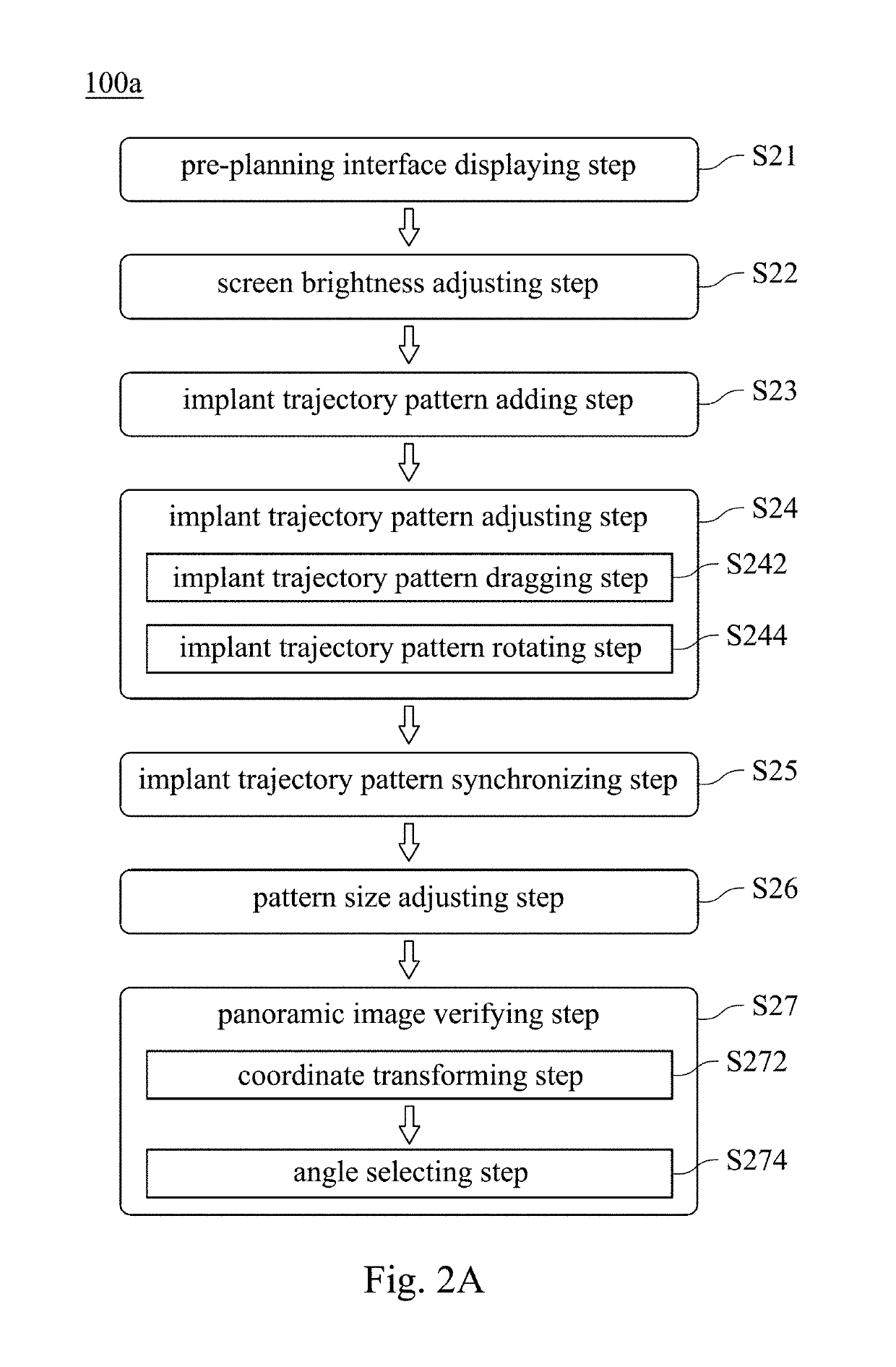
[0018]FIG. 1A shows a flow chart of a method 100 for verifying panoramic images of implants according to one embodiment of the present disclosure; FIG. 1B shows a block diagram of a system 200 for verifying panoramic images of implants according to one embodiment of the present disclosure; FIG. 3 shows a schematic view of an image of a screen 300 according to a first embodiment of the present disclosure; FIG. 4 shows a schematic view of an image of a screen according to a second embodiment of the present disclosure; FIG. 5 shows a schematic view of an image of a screen according to a third embodiment of the present disclosure; FIG. 6A shows a schematic view of an image of a screen according to a fourth embodiment of the present disclosure; FIG. 6B shows a schematic view of an image of a screen according to a fifth embodiment of the present disclosure; and FIG. 7 shows a schematic view of an image of a screen according to a sixth embodiment of the present disclosure. In addition, FIG...


PUM


Abstract

A pre-planning interface displaying step of a method for verifying panoramic images of implants is for displaying a picture, a menu and a cursor on a screen. An implant trajectory pattern adding step is for moving the cursor to select an implant adding item by a user and then generating the implant trajectory pattern in the picture. An implant trajectory pattern adjusting step is for controlling the cursor to adjust a position of the implant trajectory pattern and then move the implant trajectory pattern from a starting position to a target position in the picture. A panoramic image verifying step is for rotating the surgical site pattern around the implant trajectory pattern at a viewing angle according to the target position and the implant trajectory pattern as a central axis, and the viewing angle is greater than 0 degrees and smaller than or equal to 180 degrees.

Description

RELATED APPLICATIONS[0001]This application claims priority to U.S. Provisional Application Ser. No. 62 / 421,995 filed Nov. 14, 2016, and China application No. 201710281546.2 filed on Apr. 26, 2017, the disclosures of which are incorporated herein by reference in their entireties.BACKGROUNDTechnical Field[0002]The present disclosure relates to a method and a system for verifying images of implants. More particularly, the present disclosure relates to a method and a system for verifying panoramic images of implants.Description of Related Art[0003]In general medical institutions, a preoperative planning for surgery has already become a basic topic. Many surgical operations require high accuracy and rich experience. If there is a slight error in the surgical operation, it may cause huge damage at a surgical site.[0004]In a conventional surgical process, placement of bone screws into the human spine is a common surgical procedure to allow for a multitude of spinal surgeries to be performe...

Claims


Application Information

Patent Timeline
Patent Type & Authority Patents(United States)
IPC IPC(8): G06K9/00G06T3/40G06T3/60G06F3/0484G06F3/0482A61B90/00A61B17/70A61B34/10G06F3/0481A61B17/56
CPCA61B34/10A61B17/7001A61B90/37G06F3/0482G06F3/04845G06T3/4038G06T3/60G06T2210/41A61B2017/568A61B2034/107A61B2090/364A61B2560/0487G06F3/04815G06T2200/24A61B34/25
Inventor KAO, KUO-TUNGLIN, CHEN-TAICHENG, YING-YICHUANG, SHIH-CHANGCHIANG, CHIH-YEN
Owner REMEX MEDICAL CORP
Learn More