Movable shutter for a fluid conduit

a fluid conduit and shutter technology, applied in the direction of valve details, valve arrangement, preventing unauthorised/accidental actuation, etc., can solve the problems of fluid leakage, poor positioning, and the shutter described above providing no way to confirm the proper position of the ga

Active Publication Date: 2019-06-25
ONIS
View PDF7 Cites 1 Cited by
  • Summary
  • Abstract
  • Description
  • Claims
  • Application Information

AI Technical Summary

Benefits of technology

[0021]The invention seeks to remedy the limitations of the known movable shutters. In particular, one goal of the invention is to provide a movable shutter that allows the operator easily to ensure that the gate is properly positioned.
[0022]Another goal of the invention is to provide a movable shutter whose manufacture and installation have been simplified, thereby reducing its production costs.
[0023]Yet another goal of the invention is to provide a movable shutter that makes it possible to shift easily from a closed position to an open position and vice-versa.
[0027]a closed position in which the solid part blocks the conduit in such a way as to prevent the flow of fluid between the two half-bodies; and

Problems solved by technology

The movable shutter described above has the disadvantage of providing no way to confirm the proper position of the gate between the two plates.
Indeed, poor positioning can have serious consequences for the facility, causing fluid leaks and endangering the operators.
However, such a system is difficult to implement, because the holes in the gate must be formed in very specific positions.
Furthermore, the installation and use of the locking pin are complex, because the operator must place the pin in the proper hole.

Method used


Image

  • Movable shutter for a fluid conduit
  • Movable shutter for a fluid conduit
  • Movable shutter for a fluid conduit

Examples


first embodiment (figs.6a-6b , 7a-7d , 8 , 9a-9b , and 10)

First Embodiment (FIGS. 6a-6b, 7a-7d, 8, 9a-9b, and 10)

[0083]In the embodiments shown in FIGS. 6 through 10, the gate 1 is mounted in such a way that it can slide along a rectilinear translational direction (SX) (see FIG. 6a) that is parallel to the longitudinal median plane (S) and to the longitudinal surfaces 111, 112 of the body 11. The rectilinear translational direction (SX) is also perpendicular to the transverse median plane 14.

[0084]Thus, the sliding gate 1 can be shifted in the rectilinear translational direction (SX); that is, the gate moves between the bearing surfaces 231, 331 by means of rectilinear translation (namely, a straight linear slide) in the space between the two half-bodies 2, 3.

[0085]In this embodiment, the protruding element 15a is provided on at least one of the longitudinal surfaces 111, 112 of the body 11 of the gate 1. However, a protruding element 15a may be provided on each of the two longitudinal surfaces 111, 112.

[0086]The protruding element 15a is ...

second embodiment (figs.6c , 11 , 12a , 12b , and 13)

Second Embodiment (FIGS. 6c, 11, 12a, 12b, and 13)

[0100]In this embodiment, the protruding element 15b is provided on the bearing surface 231, 331 of at least one of the plates 23, 33. However, a protruding element 15b may be provided on each of the two bearing surfaces 231, 331.

[0101]This protruding element 15b cooperates with a recess 15c provided on the respective longitudinal surface of the body 11 (see FIG. 6c).

[0102]In the open closed position (see FIG. 12a), each protruding element 15b is placed and positioned in a corresponding recess 15c whose shape is essentially complementary, thereby allowing the bodies 2, 3 to be brought closer together. In the closed position (see FIG. 12b), each protruding element 15b is placed and positioned in a corresponding recess 15c whose shape is essentially complementary, thereby allowing the bodies 2, 3 to be brought closer together. In the default position (see FIG. 11), each protruding element 15b is placed opposite a surface 111, 112 at a ...


PUM


Abstract

A movable shutter for a fluid conduit including two half-bodies consisting of a tube that forms a conduit, to the ends of which are affixed a flange and a plate having a bearing surface; a gate with a body defined by two longitudinal surfaces located opposite the bearing surfaces, which gate is mounted movably between the bearing surfaces, between a closed position and an open position; and a locking mechanism suitable for keeping the plates in a position in which they are either separated or close together, wherein at least one protruding element is provided on at least one of the bearing surfaces or on at least one of the longitudinal surfaces, such that if the gate is not properly positioned, the protruding element forms an obstacle that prevents the locking mechanism from keeping the plates in the position in which they are close together.

Description

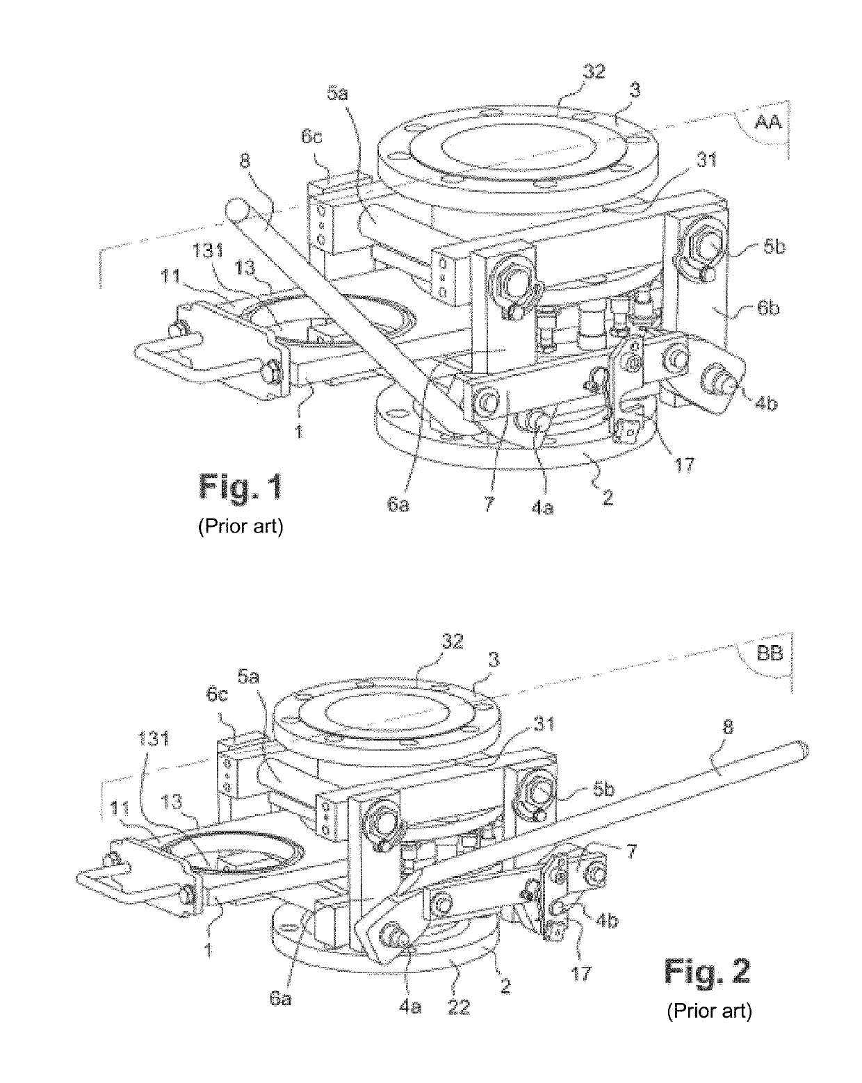
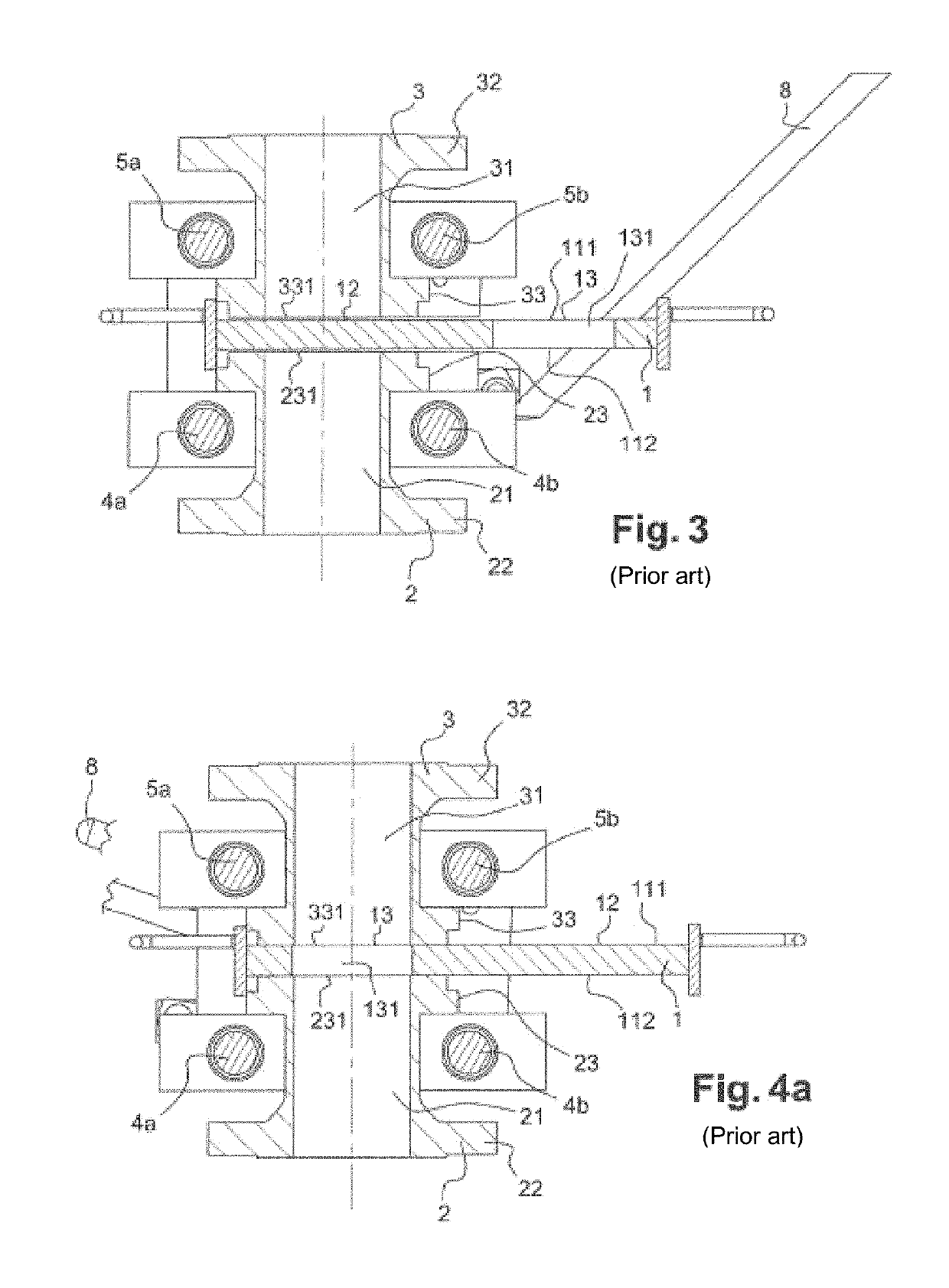
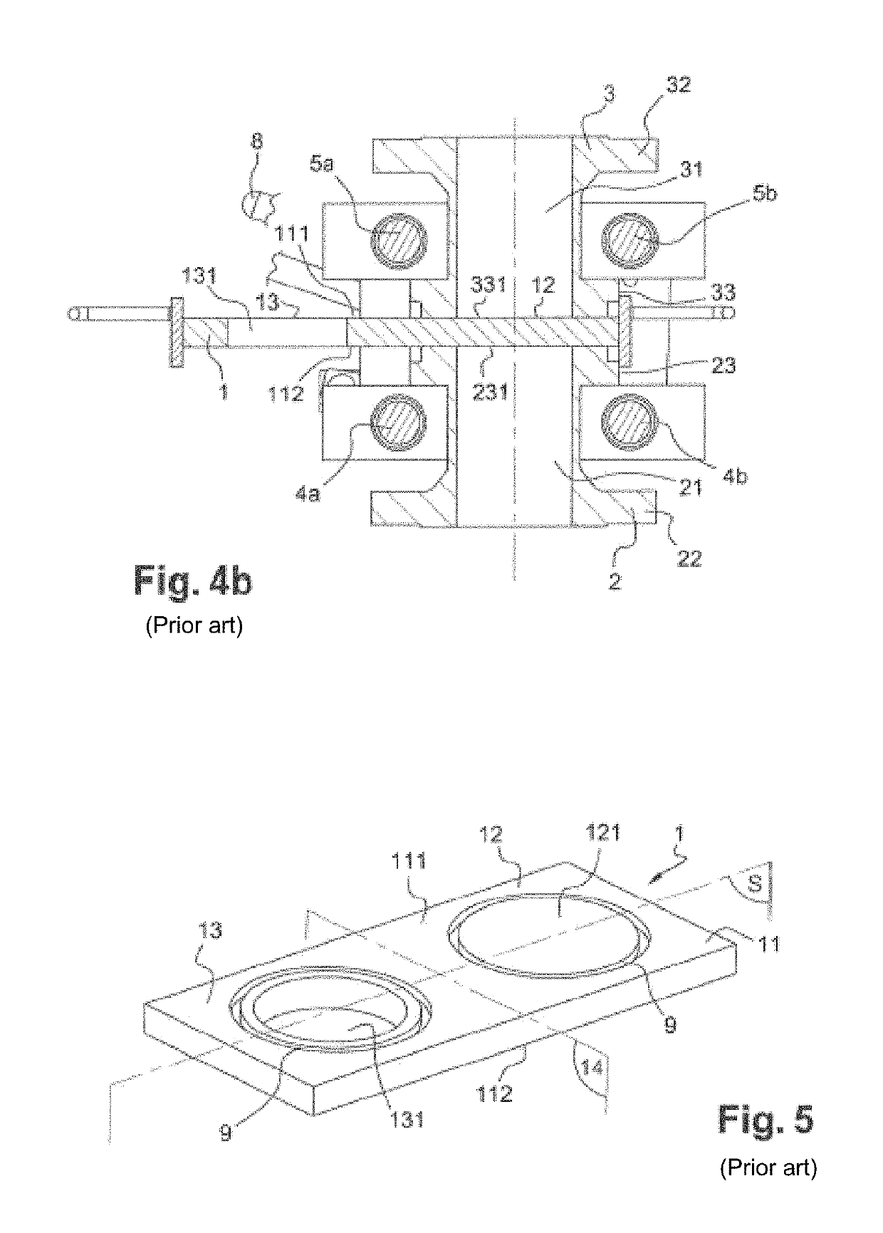
CROSS REFERENCE TO RELATED APPLICATION[0001]The present application claims priority to French patent application No. FR 15 58837, which was filed on Sep. 18, 2015.BACKGROUND OF THE INVENTION[0002](1) Field of the Invention[0003]The invention relates to the technical field consisting of equipment for various pipe networks, including, in particular, hydrocarbon refineries, gas-processing plants, and even petrochemical factories. The invention relates specifically to a movable shutter for a fluid conduit, a fluid-treatment facility, and a procedure for the secure closure of a movable shutter for a fluid conduit.[0004](2) Description of Related Art[0005]Many currently known sliding shutters allow fluid conduits to be equipped in such a way that they can shift from an open position to a closed position or vice-versa. For example, document FR 2733024 proposes the sliding shutter shown in FIGS. 1, 2, 3, 4a, and 4b. It is composed of:[0006]two half-bodies 2, 3 associated with a locking mech...

Claims


Application Information

Patent Timeline
Patent Type & Authority Patents(United States)
IPC IPC(8): F16K3/30F16K35/00F16K3/312
CPCF16K3/30F16K35/00F16K3/312F16L3/02
Inventor RIVAS, JEROME
Owner ONIS
Why Eureka
Try Eureka