Shell plate, method for making a shell plate and a grinding mill

a technology of shell plate and grinding mill, which is applied in the field of shell plate, can solve problems such as wear in the chamber

Active Publication Date: 2019-05-28
METSO OUTOTEC (FINLAND) OY
View PDF22 Cites 0 Cited by
  • Summary
  • Abstract
  • Description
  • Claims
  • Application Information

AI Technical Summary

Benefits of technology

[0005]The solid material is crushed in a drum shaped shell mounted for rotation about its central axis in the grinding mill. The axis of the rotatable shell is generally horizontally arranged or slightly inclined towards one end in the grinding mill. The interior of the shell forms a treatment chamber and has a cylindrical wall. The inner surface of the chamber is plated with a lining for protecting the shell because the material to be processed is fed to the treatment chamber and grinding it causes wear in the chamber. The interior wall of the shell is equipped with lifter bars for lifting the material inside the shell along the rotation so that as the shell rotates the shell plates lift up the solid material along the inside wall of the shell to a point where gravity causes the solid material to fall down inside the shell and by falling down the solid material is crushed. In order to protect the shell of the grinding mill shell plates are arranged in between adjacent lifter bars.
[0026]Effect of a shell plate comprising polyurethane is that the polyurethane needs less pressure and heat than other materials, such as rubber, and energy consumption can be reduced in manufacturing. Also the manufacturing process is easier because shell plate comprising polyurethane can be made using mould made from sheet metal. The shell plates can be retreated with new polyurethane when the wear surface has worn away. This retreatment can be made in smaller scale near to the factory so the need for transportation is less.

Problems solved by technology

The inner surface of the chamber is plated with a lining for protecting the shell because the material to be processed is fed to the treatment chamber and grinding it causes wear in the chamber.

Method used


Image

  • Shell plate, method for making a shell plate and a grinding mill
  • Shell plate, method for making a shell plate and a grinding mill
  • Shell plate, method for making a shell plate and a grinding mill

Examples


Embodiment Construction

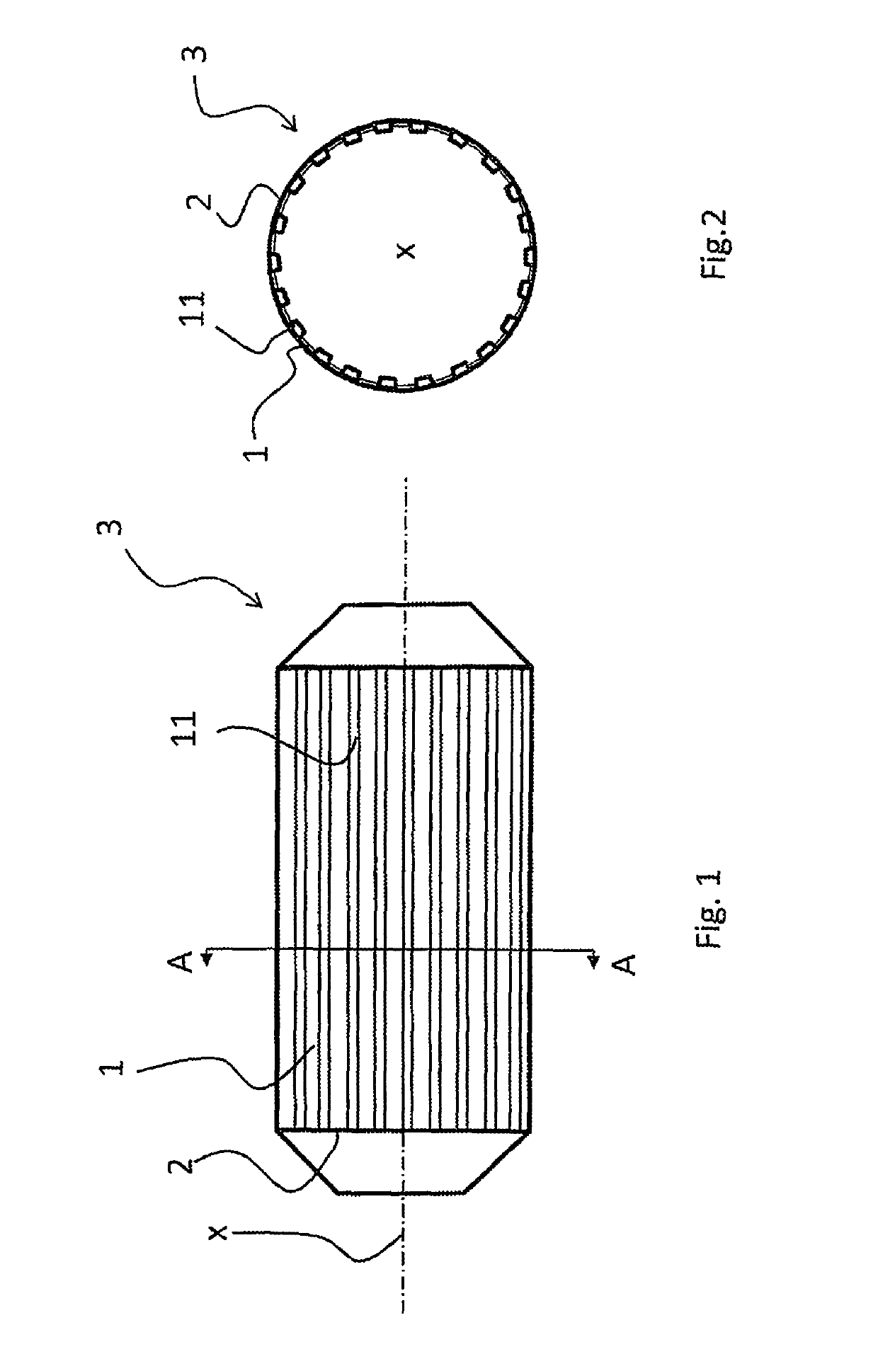
[0032]FIG. 1 shows a longitudinal cross-section of a horizontal grinding mill 3 having an inner shell 2 comprising a cylindrical wall which the shell 2 comprises lifter bars 11 mounted to the cylindrical wall of the shell 2 and in between the lifter bars 11 there are shell plates 1. The grinding mill 3 rotates about its central axis x in a predetermined direction. The axis of the shell 2 is horizontally disposed or slightly inclined toward the other end of the shell 2. The surface of the inner shell 2 is plated with shell plates 1 for protecting the drum against wear caused by grinding. The shell plates 1 is attached between the lifter bars 11 such that the lifter bars 11 and the shell plates 1 together protect the surface of the inner shell 2 of the grinding mill 3.

[0033]FIG. 2 shows a cross-section of the grinding mill 3 shown in FIG. 1 taken along line A-A. The grinding mill 3 rotates in a predetermined direction around its axis indicated by x. The shell plates 1 and the lifter b...


PUM

PropertyMeasurementUnit
thicknessaaaaaaaaaa
thicknessaaaaaaaaaa
diameteraaaaaaaaaa

Abstract

The invention relates to a shell plate, to a method for making a shell plate and to a grinding mill for ore grinding. The shell plate is mountable to a shell of a grinding mill for grinding ore and includes a shell plate body having a first portion including a fixing surface for fixing the shell plate body to the shell, and a second portion having a wear surface facing toward an interior of the grinding mill. The first portion and the second portion form a continuous shell plate body, and the second portion includes polyurethane such that the wear surface is made of polyurethane.

Description

CROSS-REFERENCE TO RELATED APPLICATONS[0001]This application is a National Phase Entry under 35 U.S.C. § 371 of PCT Patent Application Ser. No. PCT / FI2015 / 050686 filed Oct. 12, 2015, which claims priority to Finnish Patent Application No. 20145902, filed Oct. 14, 2014, the disclosure of each of these applications is expressly incorporated herein by reference in their entirety.FIELD OF THE INVENTION[0002]The invention relates to a shell plate. The invention further relates to a method for making a shell plate and to a grinding mill for ore grinding.BACKGROUND OF THE INVENTION[0003]Grinding mills are used for processing hard solid material such that large solid material is grinded into smaller pieces. Lifting bars assist in lifting the solid material that is being processed in the drum as it rotates and the shell plates' function is to protect the shell of the grinding mill.BRIEF DESCRIPTION OF THE INVENTION[0004]The shell plate according to the invention, the method for making a shel...

Claims


Application Information

Patent Timeline
Patent Type & Authority Patents(United States)
IPC IPC(8): B02C17/00B02C17/18B02C17/22B02C17/04
CPCB02C17/225B02C17/1825B02C17/04B02C17/002B29C45/14B29C45/16
Inventor LAUERMAA, KARI
Owner METSO OUTOTEC (FINLAND) OY
Why Eureka
Try Eureka