Miniature fluid control device and piezoelectric actuator thereof

a control device and miniature fluid technology, applied in the direction of machines/engines, generators/motors, positive displacement liquid engines, etc., can solve the problems of non-portability, non-miniaturization requirements of pneumatic devices or pneumatic machines, and inability to meet the miniaturization requirements, so as to enhance stability and consistence, reduce non-uniform motion, and increase the amplitude of suspension plates

Active Publication Date: 2019-05-14
MICROJET TECH
View PDF19 Cites 8 Cited by
  • Summary
  • Abstract
  • Description
  • Claims
  • Application Information

AI Technical Summary

Benefits of technology

[0005]An object of the present invention provides a piezoelectric actuator. The piezoelectric actuator comprises a suspension plate, an outer frame, four brackets and a piezoelectric ceramic plate. The brackets are perpendicularly connected between the suspension plate and the outer frame for elastically supporting the suspension plate. Such configuration can decrease the non-uniform motion such as deflecting waggling of the suspension plate, therefore increases the amplitude of the suspension plate along the Z axis, and enhances the stability and consistence of the motion of the suspension plate in the vertical direction during operation. As a result, the steadiness and performance of the piezoelectric actuator are intensified.
[0006]Another object of the present invention provides a miniature fluid control device for applying to a portable device or wearable device. The regions of a metal plate corresponding to a suspension plate, an outer frame and at least one bracket of a piezoelectric actuator are etched at the same etch depth, and thus the integral structure of the suspension plate, the outer frame and the at least one bracket is defined. Consequently, a second surface of the suspension plate, a second surface of the outer frame and a second surface of the bracket are coplanar with each other. In comparison with the conventional way using the multiple-step etching process, the process of forming the piezoelectric actuator of the present invention is simplified. In accordance with the present invention, an adhesive layer is inserted in the gap between a resonance plate and the outer frame. Since the outer frame after being etched has a rough surface, the adhesion between the adhesive layer and the outer frame is increased. Moreover, since the thickness of the outer frame decreases when compared with the outer frame of the conventional piezoelectric actuator, the thickness of the adhesive layer in the gap can be increased. The increase of the thickness of the adhesive layer enhances the coating uniformity of the adhesive layer, which decrease the assembling error of the suspension plate in the horizontal direction and improve the efficiency of utilizing the kinetic energy of the suspension plate in the vertical direction. Moreover, the increase of the thickness of the adhesive layer can assist in absorbing vibration energy and reduce noise. Due to the slim, silent and power-saving benefits, the miniature fluid control device of the present invention is suitably used in the wearable device.
[0007]A further object of the present invention provides a piezoelectric actuator of a miniature fluid control device. A suspension plate of the piezoelectric actuator is a square plate with a bulge. After an external fluid is introduced into an inlet of the gas inlet plate of a base, the fluid is guided to a central cavity through a convergence channel, and then the fluid is transferred to a compressible chamber between the resonance plate and the piezoelectric actuator through the central aperture of the resonance plate. Consequently, a pressure gradient is generated in the compressible chamber to facilitate the fluid to flow at a high speed. Since the flowrate is not reduced and no pressure loss is generated, the volume of the compressible chamber can be compressed more effectively.

Problems solved by technology

However, due to the volume limitations of the motors and the pressure valves, the pneumatic devices or the pneumatic machines are bulky in volume.
In other words, the conventional pneumatic device fails to meet the miniaturization requirement and is not portable.
Moreover, during operations of the motor or the pressure valve, annoying noise is readily generated.
That is, the conventional pneumatic device is neither friendly nor comfortable to the user.

Method used


Image

  • Miniature fluid control device and piezoelectric actuator thereof
  • Miniature fluid control device and piezoelectric actuator thereof
  • Miniature fluid control device and piezoelectric actuator thereof

Examples


Embodiment Construction

[0020]The present invention will now be described more specifically with reference to the following embodiments. It is to be noted that the following descriptions of preferred embodiments of this invention are presented herein for purpose of illustration and description only. It is not intended to be exhaustive or to be limited to the precise form disclosed.

[0021]The present invention provides a miniature fluid control device and a piezoelectric actuator thereof. The fluid control device can be used in many sectors such as pharmaceutical industries, energy industries computer techniques or printing industries for transporting fluids.

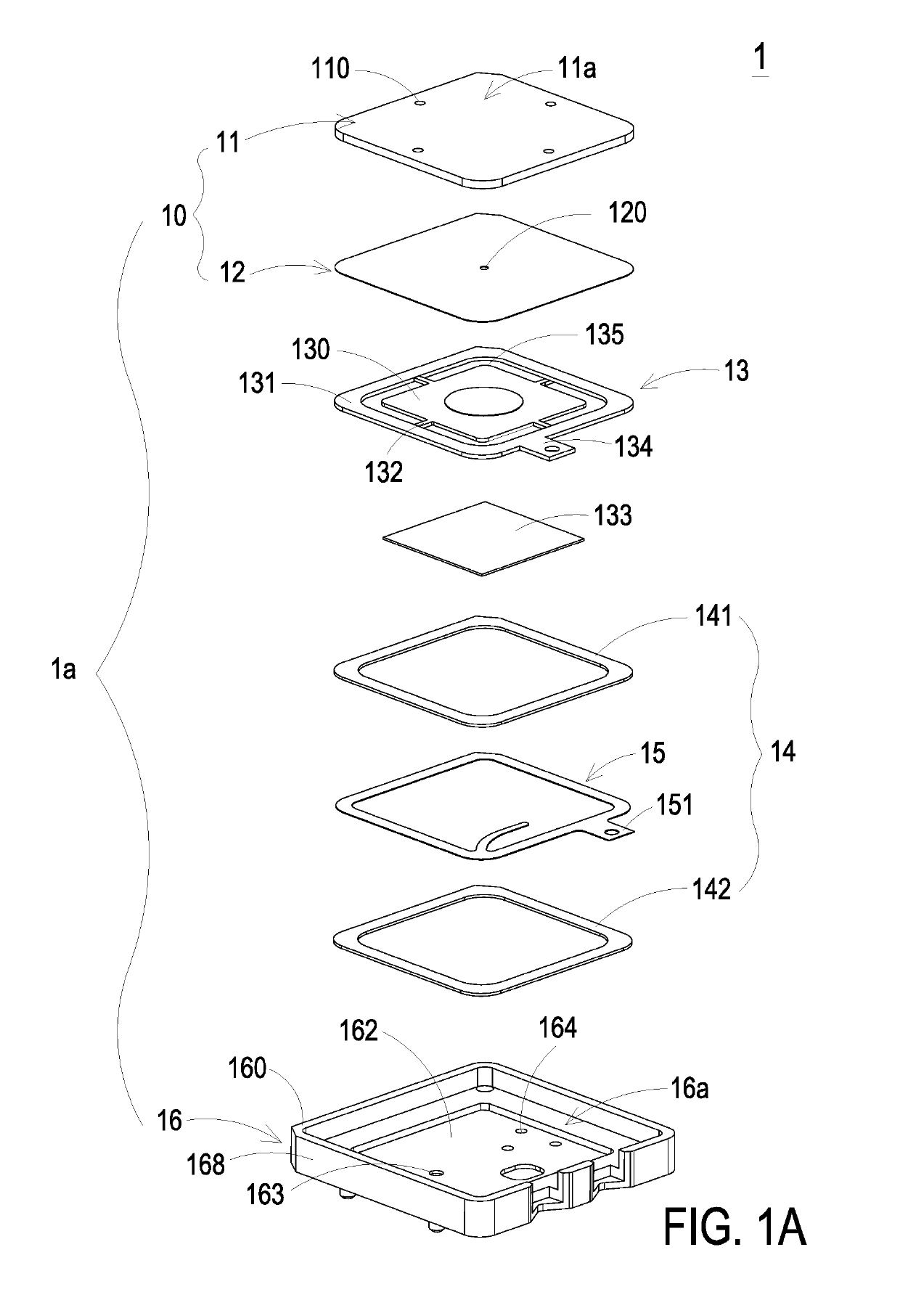
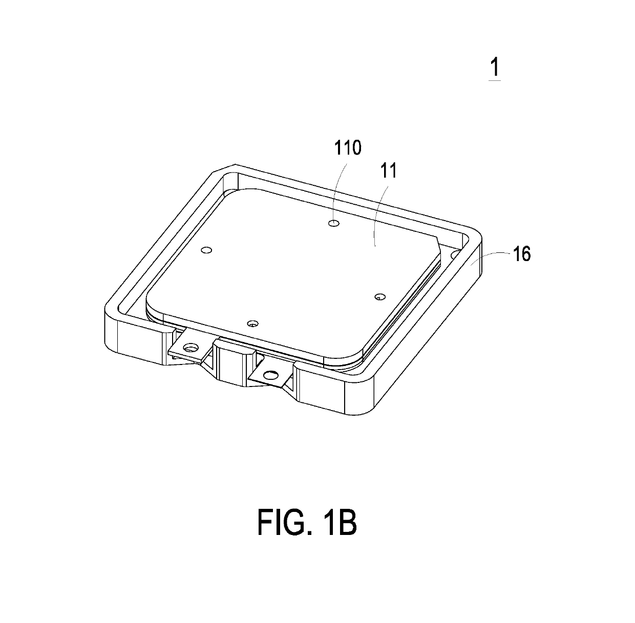
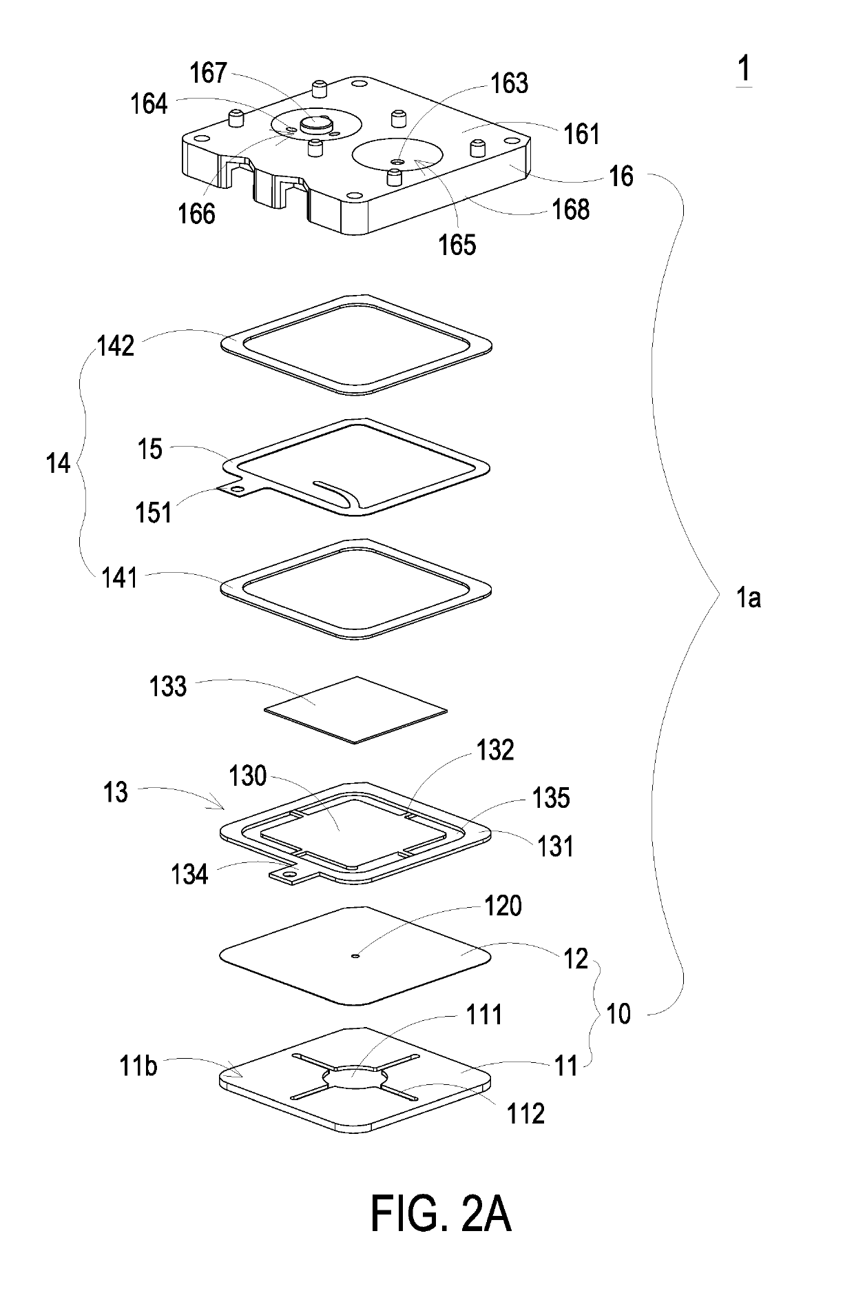
[0022]Please refer to FIGS. 1A, 1B, 2A, 2B and 5. FIG. 1A is a schematic exploded view illustrating a miniature fluid control device according to an embodiment of the present invention and taken along a first viewpoint. FIG. 1B is a schematic perspective view illustrating the assembled structure of the miniature fluid control device of FIG. 1A. FIG. 2A i...


PUM


Abstract

A piezoelectric actuator includes a square suspension plate, an outer frame, plural brackets and a square piezoelectric ceramic plate. The outer frame is arranged around the suspension plate. A second surface of the outer frame and a second surface of the suspension plate are coplanar with each other. The plural brackets are perpendicularly connected between the suspension plate and the outer frame for elastically supporting the suspension plate. Each bracket has a length in a range between 1.11 mm and 1.21 mm and a width in a range between 0.2 mm and 0.6 mm. A length of the piezoelectric ceramic plate is not larger than a length of the suspension plate. The piezoelectric ceramic plate is attached on a first surface of the suspension plate.

Description

FIELD OF THE INVENTION[0001]The present invention relates to a miniature fluid control device and a piezoelectric actuator, and more particularly to a slim and silent miniature fluid control device and a piezoelectric actuator thereof.BACKGROUND OF THE INVENTION[0002]With the advancement of science and technology, fluid control devices are widely used in many sectors such as pharmaceutical industries, computer techniques, printing industries or energy industries. Moreover, the fluid control devices are developed toward elaboration and miniaturization. The fluid control devices are important components that are used in for example micro pumps, micro atomizers, printheads or industrial printers for transporting fluid. Therefore, it is important to provide an improved structure of the fluid control device.[0003]For example, in the pharmaceutical industries, pneumatic devices or pneumatic machines use motors or pressure valves to transfer gases. However, due to the volume limitations of...

Claims


Application Information

Patent Timeline
Patent Type & Authority Patents(United States)
IPC IPC(8): F16K99/00H02N2/00F04B43/04
CPCH02N2/006H02N2/001F04B43/046F16K99/0048F04B45/047F04B45/10F04D33/00
Inventor HAN, YUNG-LUNGHUANG, CHI-FENGCHEN, SHIH-CHANGLIAO, JIA-YULIAO, HUNG-HSINHUANG, CHE-WEICHEN, SHOU-HUNG
Owner MICROJET TECH
Why Eureka
Try Eureka