Miniature fluid control device and piezoelectric actuator thereof

Active Publication Date: 2018-03-08
MICROJET TECH
View PDF17 Cites 23 Cited by
  • Summary
  • Abstract
  • Description
  • Claims
  • Application Information

AI Technical Summary

Benefits of technology

The present invention provides a piezoelectric actuator with improved stability and consistence of motion, which enhances the performance of the actuator. The actuator includes a suspension plate, an outer frame, four brackets, and a piezoelectric ceramic plate. The brackets are perpendicularly connected between the suspension plate and the outer frame for elastically supporting the suspension plate. This configuration decreases the non-uniform motion such as deflecting waggling of the suspension plate, increases the amplitude of the suspension plate along the Z axis, and intensifies the piezoelectric actuator's performance. The actuator is particularly suitable for portable or wearable devices due to its slim, silent, and power-saving benefits. A miniature fluid control device utilizing the actuator is also provided, where the device includes a suspension plate, an outer frame, brackets, and an adhesive layer for increasing the stability and consistence of motion of the suspension plate. Additionally, a piezoelectric actuator with a square plate and a bulge is provided, which facilitates the fluid to flow at a high speed and compress more effectively the volume of a compressible chamber. The actuator is not reduced in its performance even with a reduced flow rate and no pressure loss.

Problems solved by technology

However, due to the volume limitations of the motors and the pressure valves, the pneumatic devices or the pneumatic machines are bulky in volume.
In other words, the conventional pneumatic device fails to meet the miniaturization requirement and is not portable.
Moreover, during operations of the motor or the pressure valve, annoying noise is readily generated.
That is, the conventional pneumatic device is neither friendly nor comfortable to the user.

Method used


Image

  • Miniature fluid control device and piezoelectric actuator thereof
  • Miniature fluid control device and piezoelectric actuator thereof
  • Miniature fluid control device and piezoelectric actuator thereof

Examples


Embodiment Construction

[0020]The present invention will now be described more specifically with reference to the following embodiments. It is to be noted that the following descriptions of preferred embodiments of this invention are presented herein for purpose of illustration and description only. It is not intended to be exhaustive or to be limited to the precise form disclosed.

[0021]The present invention provides a miniature fluid control device and a piezoelectric actuator thereof. The fluid control device can be used in many sectors such as pharmaceutical industries, energy industries computer techniques or printing industries for transporting fluids.

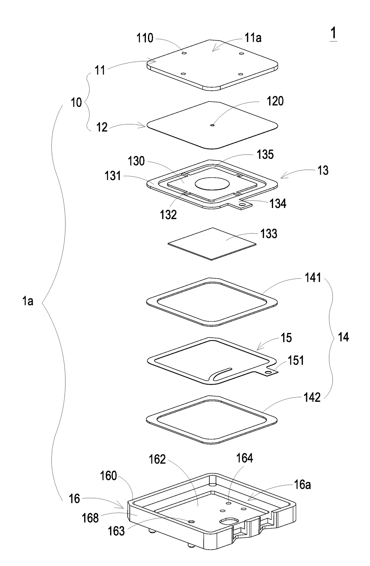
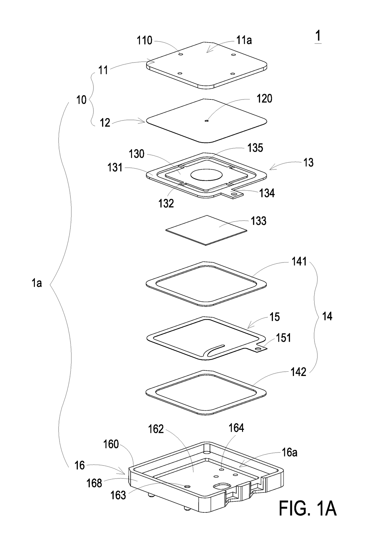
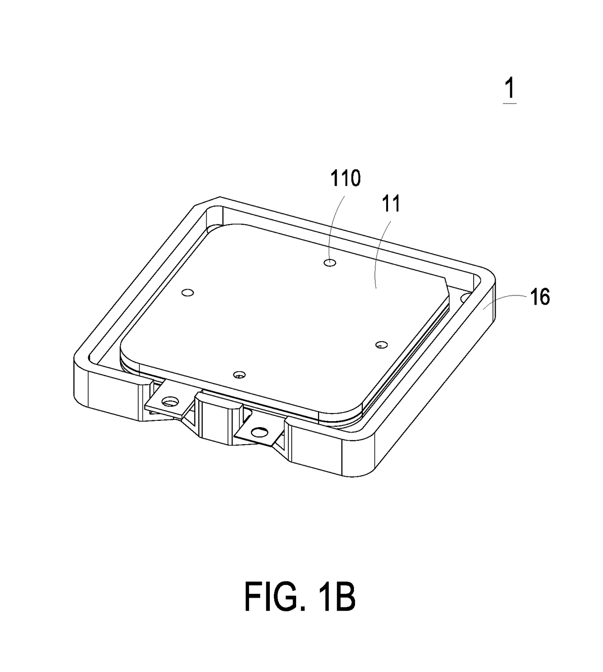
[0022]Please refer to FIGS. 1A, 1B, 2A, 2B and 5. FIG. 1A is a schematic exploded view illustrating a miniature fluid control device according to an embodiment of the present invention and taken along a first viewpoint. FIG. 1B is a schematic perspective view illustrating the assembled structure of the miniature fluid control device of FIG. 1A. FIG. 2A i...


PUM


Abstract

A piezoelectric actuator includes a square suspension plate, an outer frame, plural brackets and a square piezoelectric ceramic plate. The outer frame is arranged around the suspension plate. A second surface of the outer frame and a second surface of the suspension plate are coplanar with each other. The plural brackets are perpendicularly connected between the suspension plate and the outer frame for elastically supporting the suspension plate. Each bracket has a length in a range between 1.11 mm and 1.21 mm and a width in a range between 0.2 mm and 0.6 mm. A length of the piezoelectric ceramic plate is not larger than a length of the suspension plate. The piezoelectric ceramic plate is attached on a first surface of the suspension plate.

Description

FIELD OF THE INVENTION[0001]The present invention relates to a miniature fluid control device and a piezoelectric actuator, and more particularly to a slim and silent miniature fluid control device and a piezoelectric actuator thereof.BACKGROUND OF THE INVENTION[0002]With the advancement of science and technology, fluid control devices are widely used in many sectors such as pharmaceutical industries, computer techniques, printing industries or energy industries. Moreover, the fluid control devices are developed toward elaboration and miniaturization. The fluid control devices are important components that are used in for example micro pumps, micro atomizers, printheads or industrial printers for transporting fluid. Therefore, it is important to provide an improved structure of the fluid control device.[0003]For example, in the pharmaceutical industries, pneumatic devices or pneumatic machines use motors or pressure valves to transfer gases. However, due to the volume limitations of...

Claims


Application Information

Patent Timeline
IPC IPC(8): F16K99/00H02N2/00
CPCF16K99/0048H02N2/001H02N2/006F04B45/047F04B45/10F04D33/00
Inventor HAN, YUNG-LUNGHUANG, CHI-FENGCHEN, SHIH-CHANGLIAO, JIA-YULIAO, HUNG-HSINHUANG, CHE-WEICHEN, SHOU-HUNG
Owner MICROJET TECH
Why Eureka
Try Eureka