
Information display device

a display device and information technology, applied in the field of information display devices, can solve the problems of inactivity of rectangular display screens, inability to display navigation software output, etc., and achieve the effect of increasing the functionality of the device and not wasting power

Active Publication Date: 2019-05-07
TOMTOM INT BV
View PDF18 Cites 1 Cited by
  • Summary
  • Abstract
  • Description
  • Claims
  • Application Information

AI Technical Summary

Benefits of technology

[0007]According to the present invention, the information display device presents a user with a display that is not rectangular, as is conventional, but with a non-rectangular interface as defined by the optical frame. Furthermore, the optical frame defines at least one icon outside the rectangular display screen which can be selectively illuminated so as to provide the user with an additional information display within the non-rectangular frame. The functionality of the device is increased by the ability to illuminate one or more off-screen icons separately from illumination of the main rectangular display screen. The overall effect in the eyes of the user is a device that can display information across the non-rectangular display defined within the optical frame.
[0022]As is mentioned above, the optical element preferably comprises a touch-sensitive user interface within the non-rectangular, e.g. circular, optical frame. The touch-sensitive user interface may have a touch pad associated with each icon. The touch-sensitive user interface may comprise resistive and / or capacitive sensing methods. However, in many examples capacitive sensing is preferred to maximise the contrast of the display. The touch-sensitive user interface may comprise a printed circuit board that carries a capacitive sensor pad arranged to coincide with each icon. The capacitive sensor pad may be hollow to allow for illumination of the icon, e.g. using an aperture cut out in the printed circuit board. The printed circuit board may be flexible. It is possible for the touch-sensitive user interface to extend across the rectangular display screen so as to provide the display screen with the functionality of touch pad or touch screen inputs, but this may require electrical connection to be made between the touch-sensitive interface of the optical element and the electronic display module in order to implement touch sensitive interaction with the display screen. If anything, the touch-sensitive user interface extending across the rectangular display screen may simply allow a user to touch the display screen so as to turn it on or off. For advanced interactions, it is preferable that the electronic display module provides its own touch pad or touch screen integrated with the rectangular display screen. So as to avoid interference between the touch-sensitive user interface provided by the optical element and the rectangular display screen, it may be preferable for the optical element to be provided with a touch-sensitive user interface only in the area of the optical frame extending outside the rectangular display screen. If the rectangular display screen does not have its own touch sensitive input functionality then the touch-sensitive interface in the optical frame may provide the primary means of user input for the device. A user may therefore input information to the device by touching one or more of the icons that are illuminated in the optical frame outside of the rectangular display screen. The touch-sensitive interface is preferably connected to the electronic controller for the illumination means.

Problems solved by technology

However, it may not be necessary or desirable for an output of the navigation software to be displayed at all times, and therefore the rectangular display screen may be inactive when navigation functionality is not being used.

Method used


Image

  • Information display device
  • Information display device
  • Information display device

Examples


Embodiment Construction

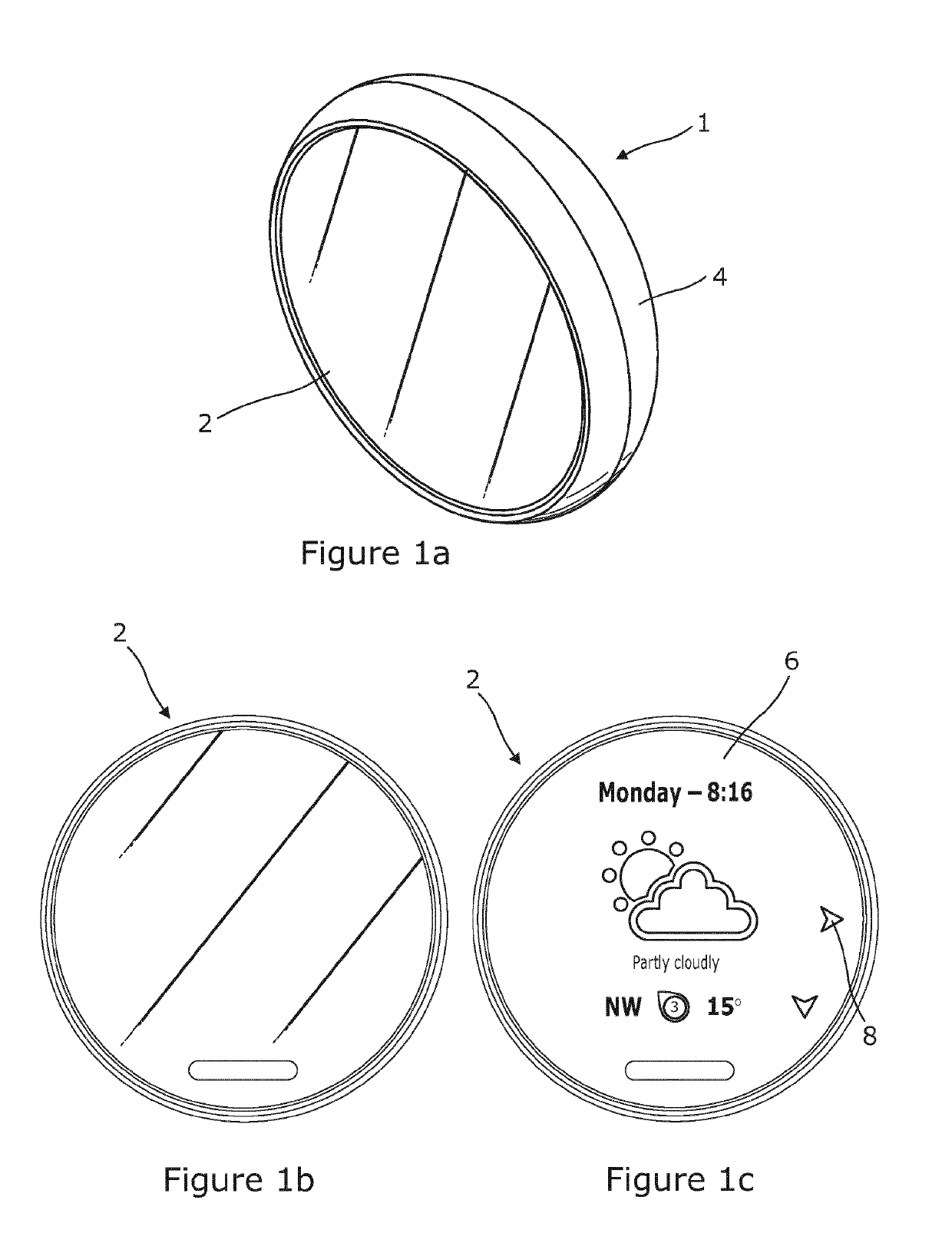
[0039]There is seen in FIG. 1a a portable information display device 1 which has a substantially flat and circular display 2 carried at the front of a rounded housing 4. When the circular display 2 is not in use, it has the visual appearance of a uniformly dark disc, as is seen from FIG. 1b. When the display is in use, as is shown in FIG. 1c, it has the appearance of a continuous circular display with illuminated images on a central display screen 6 being surrounded by at least one illuminated icon 8 outside the display screen 6. The illuminated icon(s) 8 actually occupy an optical frame extending outside the underlying rectangular outline of the display screen 6, but this is not readily discernable when viewing the display 2. Although not shown, at other times the central display screen 6 may be turned off while one or more of the icons 8 may still be illuminated.

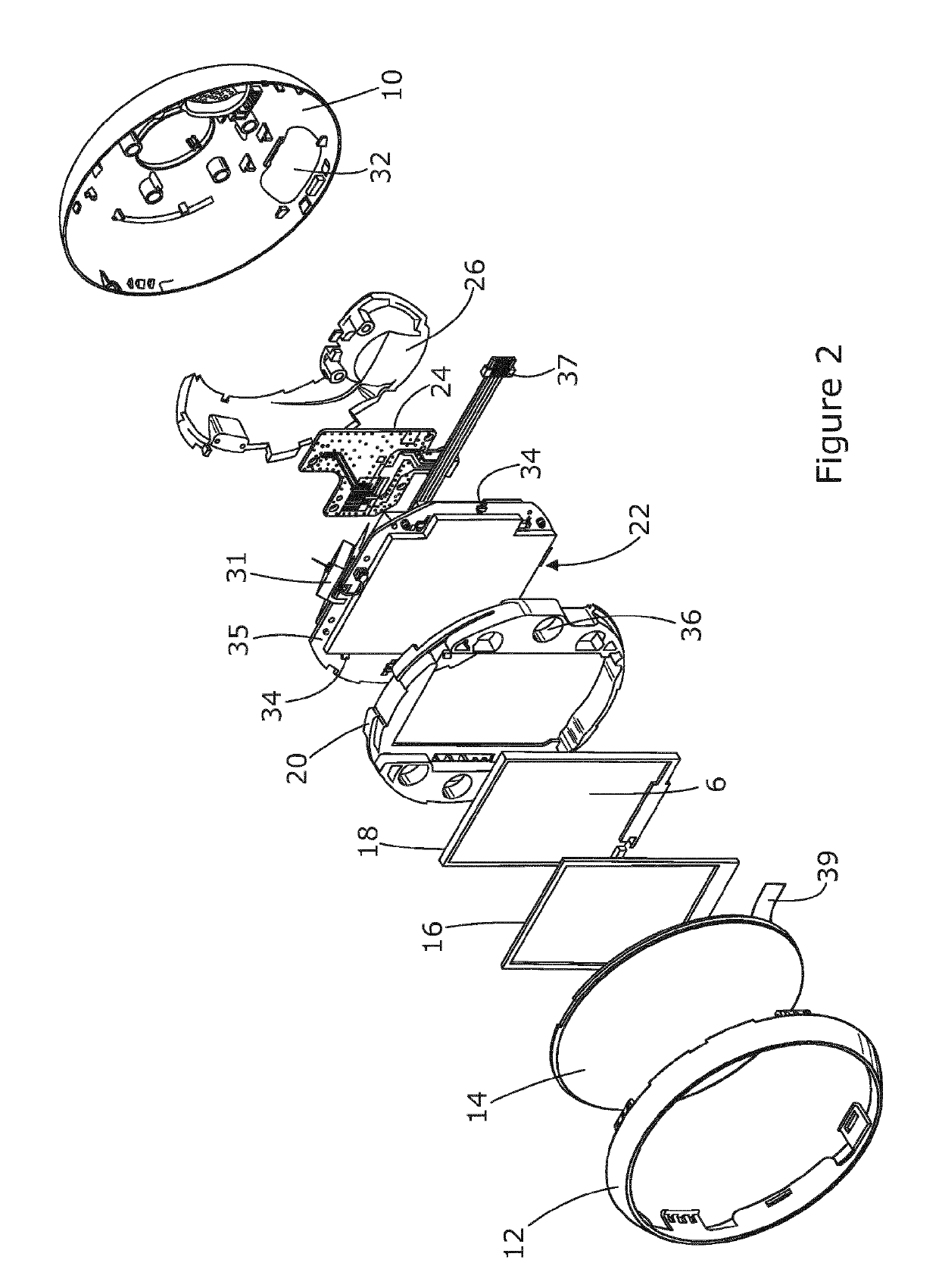
[0040]The components that make up the information display device 1 are seen in more detail in FIG. 2. The outer housing ...


PUM


Abstract

A portable information display device 1 is disclosed comprising an electronic display module 2 comprising a substantially rectangular display screen 6 and an optical element 14 arranged in front of the electronic display module to form a non-rectangular optical frame extending outside the rectangular display screen. Illuminating means 22, 34 behind the optical frame is arranged to illuminate at least one icon 8 defined by the optical element outside the rectangular display screen, and an electronic controller 24 for the illuminating means is arranged to selectively illuminate the at least one icon outside the rectangular display screen.

Description

CROSS-REFERENCE TO RELATED APPLICATIONS[0001]The present application is a National Stage of International Application No. PCT / EP2014 / 057981, filed April 17, 2014 and designating the United States, which claims benefit to United Kingdom Patent Application Serial No. GB1306989.3 filed on April 17, 2013. The entire content of these applications are incorporated herein by reference.FIELD OF THE INVENTION[0002]The present invention relates to information display devices, and particularly to mobile or portable information display devices. Illustrated embodiments of the invention may relate to portable information display devices including mobile phones, smart phones, PDAs, tablet computers, other handheld personal computers, and portable navigation devices (so-called PNDs).BACKGROUND TO THE INVENTION[0003]Information display devices, and in particular portable information display devices, have become commonplace in everyday life for the purposes of communication, navigation, entertainment...

Claims


Application Information

Patent Timeline
Patent Type & Authority Patents(United States)
IPC IPC(8): G09G5/10G01C21/26G04G17/08G06F3/0354G06F3/0482G06F3/041G04G17/04G06F3/0481G06F3/02G04G21/00G04G9/00
CPCG09G5/10G01C21/265G04G17/045G04G17/08G06F3/0202G06F3/03547G06F3/041G06F3/0482G06F3/04817G06F3/0219G04G21/00G04G9/0064G06F3/0393
Inventor BROADBENT, SAMUEL MARKTATTERSFIELD, ANDREW JOHN ROYEVANS, NICHOLAS ALEXANDER
Owner TOMTOM INT BV
Learn More