
Patient monitor with user-defined monitored parameters

a patient monitor and user-defined technology, applied in the field of medical monitoring arts, can solve the problems of not providing medical personnel with additional information, limited medical personnel to the monitoring units and derived parameters provided, etc., to improve the appropriateness of biometric parameters, improve patient monitoring flexibility, and enhance the effect of information provided

Active Publication Date: 2019-04-23
KONINKLJIJKE PHILIPS NV
View PDF22 Cites 0 Cited by
  • Summary
  • Abstract
  • Description
  • Claims
  • Application Information

AI Technical Summary

Benefits of technology

Enhances patient monitoring flexibility, appropriateness of biometric parameters, and provides enhanced information to medical personnel, improving their ability to respond to patient conditions by allowing the creation and monitoring of custom biometric parameters.

Problems solved by technology

However, medical personnel are limited to those monitoring units and derived parameters provided by the monitoring system.
However, this approach does not provide medical personnel with additional information except upon occurrence of the selected alarm threshold.

Method used


Image

  • Patient monitor with user-defined monitored parameters
  • Patient monitor with user-defined monitored parameters

Examples


Embodiment Construction

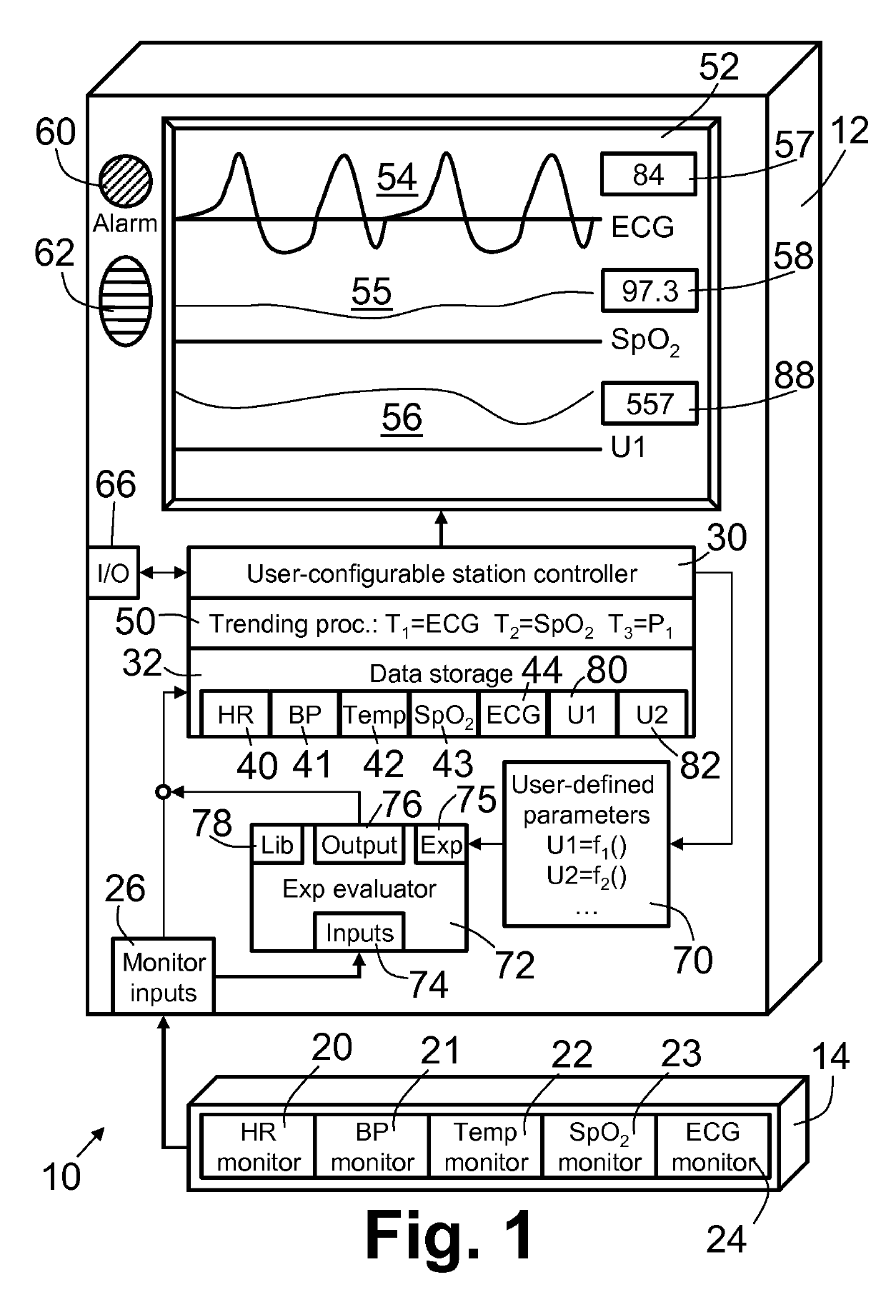
[0020]With reference to FIG. 1, a medical monitoring system 10 includes a monitoring station 12 operatively connected with a modular biometric monitor rack 14. The rack 14 includes an example heart rate (HR) monitor module 20 configured to monitor patient heart rate, an example blood pressure monitor module 21 configured to monitor patient blood pressure, an example temperature monitor module 22 configured to monitor patient temperature, an example blood oxygen saturation (SpO2) monitor module 23 configured to monitor patient blood oxygen saturation level, and an example electrocardiographic (ECG) monitor module 24 configured to monitor patient cardiac cycling. Additional, fewer, or other biometric parameters can be monitored. In some embodiments, a single monitor, which may or not be modular, is configured to monitor more than one biometric parameter.

[0021]Each of the biometric monitors 20, 21, 22, 23, 24 collects samples that are communicated to a monitoring inputs portion 26 of t...


PUM


Abstract

In a medical monitoring system, one or more biometric monitors collect data of a plurality of monitored biometric parameters. An expression evaluator evaluates a user-defined expression incorporating one or more of the monitored biometric parameters to generate data for a user-defined biometric parameter. A further processing component performs processing and display of data of at least one parameter selected from the monitored biometric parameters and the user-defined biometric parameter. The further processing component operates in the same way regardless of whether the at least one parameter is selected from the monitored biometric parameters or the user-defined biometric parameter.

Description

CROSS REFERENCE TO RELATED APPLICATIONS[0001]This is a continuation of prior application Ser. No. 12 / 094,213 filed May 19, 2008, which is a national filing of PCT application Serial No. PCT / IB2006 / 054016, filed Oct. 20, 2006, published as WO 2007 / 060559 A2 on May 31, 2007, which claims the benefit of U.S. provisional application Ser. No. 60 / 739,744 filed Nov. 23, 2005, which is incorporated herein by reference.BACKGROUND[0002]The following relates to the medical monitoring arts. It finds particular application in bedside patient monitoring in clinical settings such as hospitals, intensive care units (ICU), cardiac care units (CCU), and so forth, and will be described with particular reference thereto. However, it also finds more general application in medical monitoring generally, including fetal monitoring, neonatal monitoring, pediatric monitoring, surgical patient monitoring, outpatient monitoring, home monitoring, veterinary monitoring, monitoring during aerobic workouts, and so...

Claims


Application Information

Patent Timeline
Patent Type & Authority Patents(United States)
IPC IPC(8): A61B5/0205A61B5/00G16H10/20A61B5/145A61B5/0402A61B5/021A61B5/024G16H40/63
CPCG16H40/67A61B5/02055A61B5/00A61B5/0402A61B5/14542A61B5/742A61B5/7475G16H10/20A61B5/021A61B5/024G16H40/63A61B5/318
Inventor NIELSEN, LARRYSAEED, MOHAMMED
Owner KONINKLJIJKE PHILIPS NV
Learn More