
Ink jet method and ink jet apparatus

a technology of ink jet and ink jet, which is applied in the direction of liquid degasification, separation processes, inks, etc., can solve the problems of ejection direction and/or ejection amount being liable to be unstable, and achieve excellent durability, improve ejection stability, and improve the durability of the dissolved gas amount control unit.

Active Publication Date: 2019-04-16
SEIKO EPSON CORP
View PDF9 Cites 0 Cited by
  • Summary
  • Abstract
  • Description
  • Claims
  • Application Information

AI Technical Summary

Benefits of technology

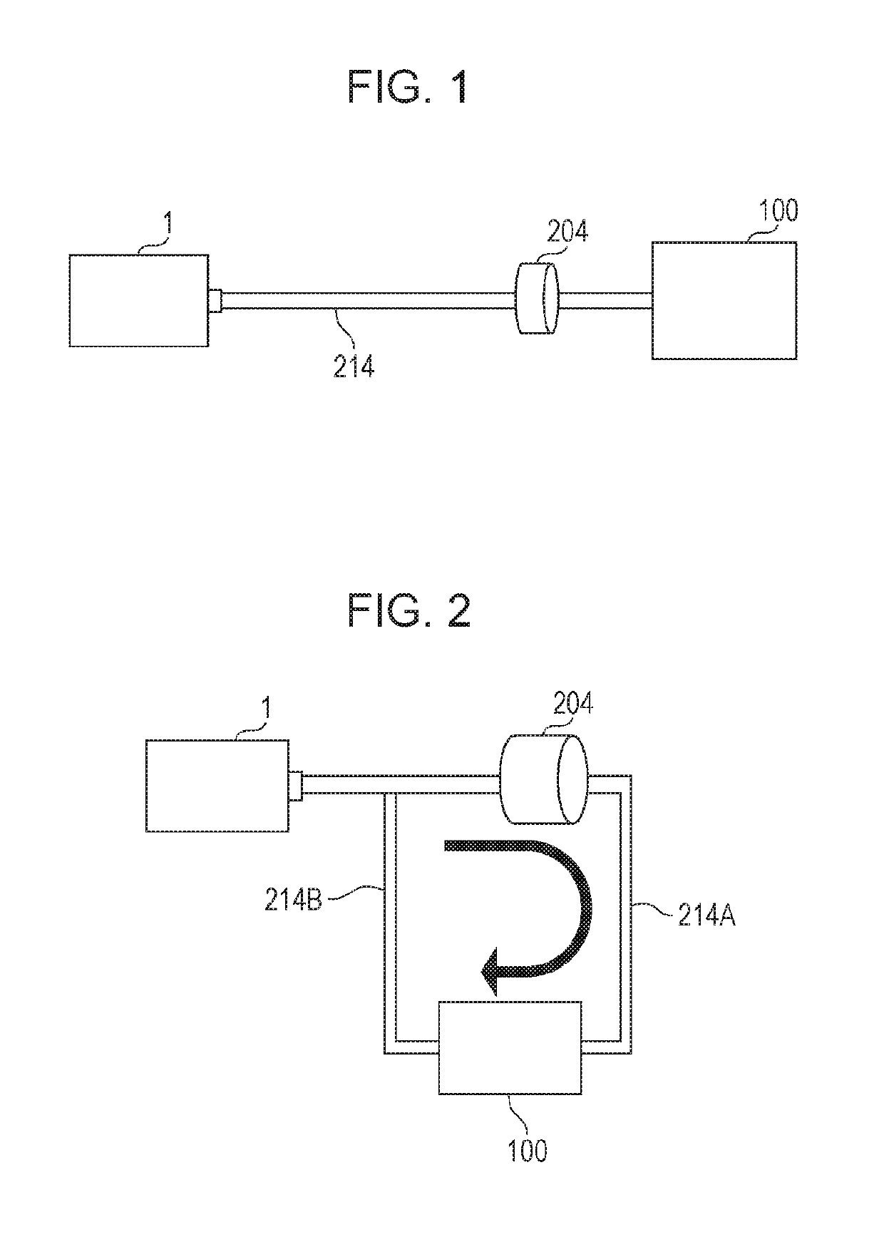
The invention is an ink jet composition that can be used by ejection using an ink jet method. The composition can be used in various applications such as ink application and polymer formation. The invention is superior in terms of the durability of the dissolved gas amount control unit, which prevents degradation and unstable ejection direction and amount. The difference in the mass average SP value between the polymerizable compound and the adhesive in the dissolved gas amount control unit is 1.0 or more, which further improves the durability of the control unit. The dissolved gas amount in the composition is controlled by adjusting the difference between the mass average SP value of the polymerizable compound and the SP value of the adhesive. The absolute value of the difference is preferably 1.0 to 20 mass ppm. The dissolved gas amount is adjusted by methods such as adjusting the container and ink jet head or adjusting the amount of polymerizable compound in the composition. The composition has excellent storage stability and curing property. The dissolved gas amount in the composition is preferably 1.0 to 20 mass ppm. The invention provides a solution for improving the durability of the dissolved gas amount control unit and controlling the dissolved gas amount in the composition.

Problems solved by technology

When the dissolved gas amount control unit is degraded, since the function of controlling a dissolved gas amount of the composition is degraded, the gas amount dissolved in the composition is out of an appropriate range, and an ejection direction and / or an ejection amount thereof is liable to be unstabilized.
In addition, the composition may flow out through the cracks in some cases.

Method used


Image

  • Ink jet method and ink jet apparatus
  • Ink jet method and ink jet apparatus

Examples


examples

[0128]Hereinafter, although this embodiment will be described in more detail with reference to examples and comparative examples, this embodiment is not limited thereto as long as not departing from the scope thereof.

[0129]Main structures and materials used for an ink jet apparatus, a dissolved gas amount control unit, and an ink jet composition, each of which is used in the following examples and comparative examples, are described below.

Ink Jet Apparatus

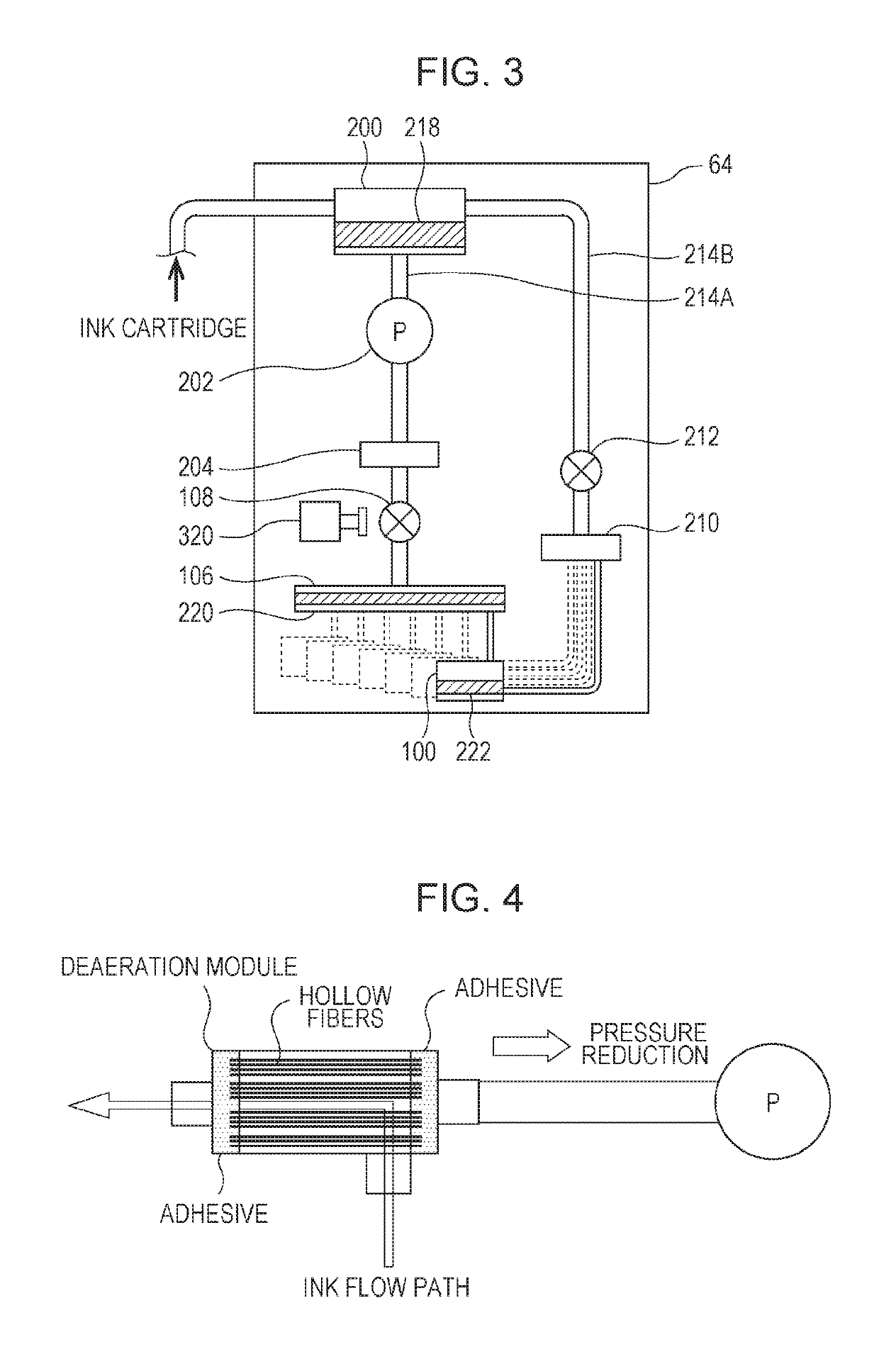
[0130]An ink jet printer PX-7500 (manufactured by Seiko Epson Corporation) modified to have the internal structure of the ink jet apparatus shown in FIG. 3 was prepared.

Dissolved Gas Amount Control Unit

[0131]A hollow fiber deaeration module (modified “EF-G3”, trade name, manufactured by DIC Corporation, hereinafter, abbreviated as “deaeration module”) was incorporated in a part of a flow path with joints.

Heating Device

[0132]A heating device (not shown) was incorporated in a part of the flow path with joints at an upstream side of t...


PUM

PropertyMeasurementUnit
pressure lossaaaaaaaaaa
viscosityaaaaaaaaaa
temperatureaaaaaaaaaa

Abstract

An ink jet method includes a dissolved gas amount control step of controlling a dissolved gas amount of a radiation curable ink jet composition by a dissolved gas amount control unit at least a part of a flow path connecting a container receiving the ink jet composition and an outlet of an ink jet head to which the ink jet composition is supplied from the container; and an ejection step of ejecting the ink jet composition from the outlet of the ink jet head. The ink jet composition contains a polymerizable compound and a polymerization initiator, the dissolved gas amount control unit includes a member formed from an adhesive, and an absolute value (|(σ1)−(σ2)|) of the difference between a mass average SP value (σ1) of the polymerizable compound and a SP value (σ2) of the adhesive, each of which is calculated by Small's formula, is 1.0 or more.

Description

BACKGROUND1. Technical Field[0001]The present invention relates to an ink jet method and an ink jet apparatus.2. Related Art[0002]Since an ink jet recording method is able to record a highly fine image by a relatively simple apparatus, techniques relating to this recording method have been rapidly developed in various fields. In particular, in order to more stably obtain a high quality recorded material, various studies have been carried out.[0003]In order to provide a deaeration method for an ink jet ink which is excellent in productivity, storage stability, ejection property, and granularity in printing but which is a highly viscous pigment ink, for example, JP-A-2013-237276 has disclosed a deaeration method for an ink jet ink containing at least a pigment and having a viscosity of 10 to 50 mPa·sec at 25° C. In this method, the deaeration is performed using an external reflux type hollow fiber deaeration module under conditions in which the pressure loss of the hollow fiber deaera...

Claims


Application Information

Patent Timeline
Patent Type & Authority Patents(United States)
IPC IPC(8): B41J2/19B41J2/175C09D11/101B41J2/18B01D19/00C09D11/322B41J11/00
CPCB41J2/19B01D19/0063B41J2/17596C09D11/101B41J2/18C09D11/322B41J11/002B01D19/0031
Inventor NAKANO, KEITAROANDO, MASAAKISAITO, TORUTSUCHIYA, HITOSHIYODA, TOSHIYUKI
Owner SEIKO EPSON CORP
Learn More