Sensor for measuring angular position, and measurement compensation method

a technology of angular position and sensor, applied in the direction of instruments, electric control, ignition automatic control, etc., can solve problems such as erroneous measurement of tim

Active Publication Date: 2019-03-19
VITESCO TECH GERMANY GMBH
View PDF31 Cites 1 Cited by
  • Summary
  • Abstract
  • Description
  • Claims
  • Application Information

AI Technical Summary

Benefits of technology

[0011]One problem to be solved by the present invention is to achieve a precise reference measurement at a given time t1, comprising a measurement of angular position and a measurement of time that are simultaneous, with a software device having standard performance characteristics and, at the most, one hardware acquisition device.

Problems solved by technology

However, by reason of the time delay 5, this acquisition is only carried out at a later time t2 and leads to an erroneous measurement of time T2.

Method used


Image

  • Sensor for measuring angular position, and measurement compensation method
  • Sensor for measuring angular position, and measurement compensation method

Examples


Embodiment Construction

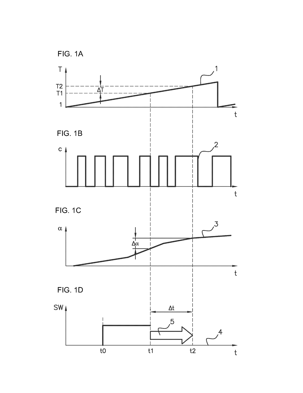
[0031]FIGS. 1A, 1B, 1C, and 1D illustrate the various quantities used in the above context presented on diagrams, disposed for comparison as a function of time t.

[0032]It is assumed here that, in order for example to be able to synchronize a mechanical event with an engine control software application, for a given moment in time t1, a double reference measurement, comprising a measurement of the time T1 and a measurement α of the angular position at this time t1, is obtained.

[0033]A measurement of the time T is obtained by means of a timer or clock producing a linear signal T as a function of time t, such as is shown on the FIG. 1A. Such a signal T is typically produced by a counter whose value is regularly incremented as a function of time. A counter typical comprises 24 bits and thus allows counting with a period T0 of 1024, between 0 and 1024−1. At the end of this period, the counter is reset to zero, as illustrated on the right of the FIG. 1A, and re-starts its count. Such a res...


PUM


Abstract

Method for compensating a reference measurement including a measurement of angular position α and a measurement of time T1 that are simultaneous at the time t1, for an angular position sensor of the type including a toothed wheel, includes the following steps: determination of a first measurement α of corresponding angular position at the moment in time t1 when a reference measurement is desired; triggering of a software acquisition function; substantially simultaneous acquisitions of a second measurement α′ of the angular position and of a measurement T2 of the time by software acquisition at a time t2; estimation of an error ΔT; and calculation of the compensated measurement of time, T1=T2−ΔT. A Sensor for measuring angular position, of the type including a toothed wheel, implementing such a compensation method is described.

Description

[0001]The present invention relates to a sensor for measuring angular position, of the type comprising a toothed wheel and a method for compensating its measurement.BACKGROUND OF THE INVENTION[0002]A known solution for carrying out a measurement of the angular position of a rotating element is by equipping said rotating element with a toothed wheel with a detector, disposed facing it on a fixed structure, designed to detect the presence or the absence of a tooth. Such a detector, when the rotating element and hence the toothed wheel rotate, allows a crenelated signal c of the type shown, as a function of the time t, on the diagram 2 in FIG. 1B to be obtained. Such a signal c can be processed by integration or by counting of the teeth in order to obtain a signal a of the type shown, as a function of the time t, on the diagram 3 in FIG. 1C, which is indicative of the angular position α of said rotating element.[0003]Such a sensor is conventionally used in the field of the control of i...

Claims


Application Information

Patent Timeline
Patent Type & Authority Patents(United States)
IPC IPC(8): G05B13/02G05B15/02G05B99/00F02P5/15F02D1/16G01D21/00G04F10/00G06F17/40G01B7/30G05B11/01F02P7/067G01D5/244F02D41/00
CPCG01B7/30F02P7/067G01D5/24476G05B11/011F02D1/16G06F17/40F02P5/15G01D21/00G05B13/02G05B15/02G05B99/00F02D41/009G16Z99/00
Inventor BAISSAC, JEAN-MARC
Owner VITESCO TECH GERMANY GMBH
Why Eureka
Try Eureka