Pendulum damping system equipped with support member having raceways juxtaposed continuously around rotation axis

a technology of support member and pendulum, which is applied in the direction of spring/damper, rotational vibration suppression, vibration suppression adjustment, etc., can solve the problems of vibration entering the gearbox, undesirable noise, impacts, acoustic emissions, and impacts between the pendulum flyweight and the support member, etc., to achieve simple, economical, and effective

Active Publication Date: 2019-03-19
VALEO EMBRAYAGES SAS
View PDF7 Cites 0 Cited by
  • Summary
  • Abstract
  • Description
  • Claims
  • Application Information

AI Technical Summary

Benefits of technology

[0007]An idea on which the invention is based is to provide a simple, economical, and effective solution to these problems.
[0013]If the deflection of the pendulum flyweights exceeds the deflection caused by guidance of the rolling bodies on the associated first outer raceways, the rolling bodies of the pendulum flyweights thus pass freely to adjacent outer raceways, so that the deflection of the pendulum flyweights with respect to the support member is not limited, and it is no longer necessary to provide abutment elements made of elastomeric material (which are complex and costly), allowing acoustic emissions to be limited when the pendulum oscillator is subjected to vibrations whose amplitude results in saturation.
[0021]The internal ring is covered with a ring of elastomeric material in order to damp the fall of the pendulum flyweights when the pendulum flyweights are no longer subjected to centrifugal force.

Problems solved by technology

Otherwise vibrations would enter the gearbox and produce particularly undesirable noise, impacts, and acoustic emissions therein during operation.
These operating conditions result, each time, in impacts between the pendulum flyweights and the support member.
Elastomer abutment elements of this kind are subjected, however, to high temperatures and to a large number of impacts.
Elastomer abutment elements of this kind thus result in a limitation of the service life of the damping system, and in an increase in the system's cost and complexity.

Method used


Image

  • Pendulum damping system equipped with support member having raceways juxtaposed continuously around rotation axis
  • Pendulum damping system equipped with support member having raceways juxtaposed continuously around rotation axis
  • Pendulum damping system equipped with support member having raceways juxtaposed continuously around rotation axis

Examples


Embodiment Construction

)

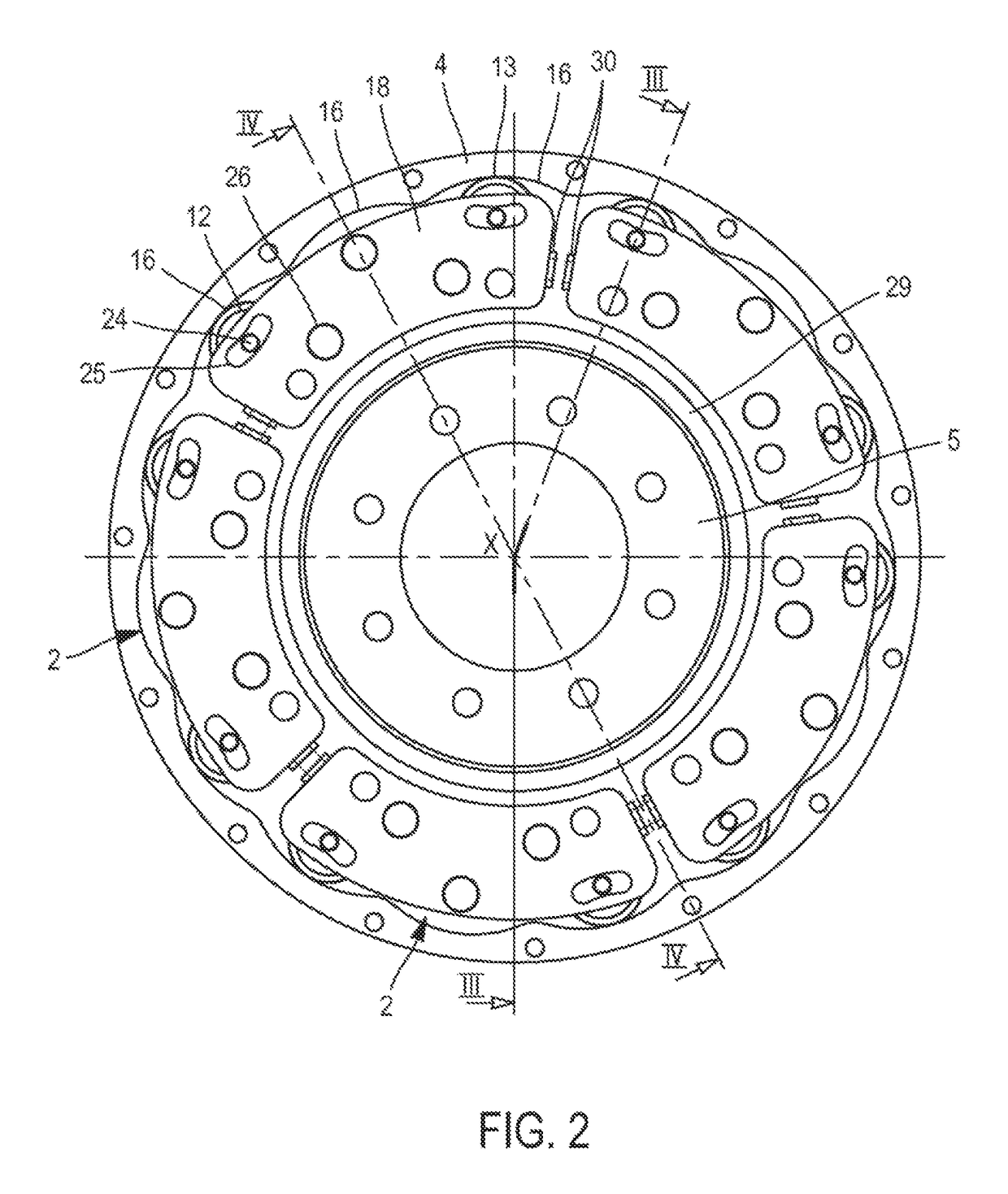
[0040]In the description and the claims, the terms “outer” and “inner” and the “axial” and “radial” orientations will be used to designate elements of the damping system in accordance with the definitions given in the description. By convention, the “radial” orientation is directed orthogonally to the rotation axis X of the damping system determining the “axial” orientation; and, moving away from said axis from inside to outside, the “circumferential” orientation is directed orthogonally to the axis of the damping system and orthogonally to the radial direction. The terms “outer” and “inner” are used to define the relative position of one element with respect to another with reference to the axis X of the damping system; an element close to the axis is thus referred to as “inner,” as opposed to an “outer” element situated radially at the periphery.

[0041]The vibration damping system is intended to be arranged in the transmission drivetrain of a motor vehicle between the combustion e...


PUM


Abstract

The invention relates to a vibration damping system for a motor vehicle transmission, comprising:a support member (1) capable of being driven rotationally around an axis X and having a plurality of outer raceways (16); anda plurality of pendulum flyweights (2) distributed circumferentially around the axis X;each of the pendulum flyweights (2) being mounted oscillatingly with respect to the support member (1) by means of two rolling bodies (12, 13) that interact respectively with one and the other of the two inner raceways (14, 15) of the pendulum flyweight (2) and each interact with one of the outer raceways (16) of the support member (1),the outer raceways (16) being juxtaposed one after another continuously around the axis X, so that the rolling bodies (12, 13) are each capable of passing freely from a first outer raceway (16) to a second outer raceway (16).

Description

CROSS-REFERENCE TO RELATED APPLICATIONS AND CLAIM TO PRIORITY[0001]This application is a national stage application of International Application No. PCT / EP2015 / 073117 filed Oct. 7, 2015, which claims priority to French Patent Application No. 1459983 filed Oct. 17, 2014, the disclosures of which are incorporated herein by reference and to which priority is claimed.FIELD OF THE INVENTION[0002]The invention relates to the field of vibration damping systems of the pendulum oscillator type, intended to be installed on motor vehicle transmissions.BACKGROUND OF THE INVENTION[0003]A combustion engine exhibits irregularities due to the combustion events occurring sequentially in the engine's cylinders, the frequency of the irregularities varying in particular as a function of the number of cylinders and the rotation speed of the engine. The function of a damping system is to filter the vibrations caused by the irregularities upstream from the gearbox. Otherwise vibrations would enter the gea...

Claims


Application Information

Patent Timeline
Patent Type & Authority Patents(United States)
IPC IPC(8): F16F15/14
CPCF16F15/145F16F15/1485
Inventor VERHOOG, ROELGRIECO, GIOVANNI
Owner VALEO EMBRAYAGES SAS
Why Eureka
Try Eureka