System and method to filter engine signals

a technology of engine signals and filtering methods, applied in the direction of machines/engines, fuel injection control, electric control, etc., can solve the problem of exhibiting a standard deviation that is larger than desired, and achieve the effect of tight control of engine air-fuel ratio, eliminating or reducing frequency signal strength, and improving engine air-fuel control

Active Publication Date: 2019-02-12
FORD GLOBAL TECH LLC
View PDF8 Cites 5 Cited by
  • Summary
  • Abstract
  • Description
  • Claims
  • Application Information

AI Technical Summary

Benefits of technology

[0005]By adjusting coefficients of a finite impulse response filter or an infinite impulse response filter responsive to engine induction ratio, it may be possible to provide the technical result of providing a filtered engine signal that has a desired level of dynamic response with a desired standard deviation even when an engine is operated with an induction ratio that is less than one. When an engine signal is filtered according to the present description, the filtered engine signal may have a desired standard deviation that allows engine air-fuel ratio to be tightly controlled. Further, other engine actuators, such as camshafts and intake throttles, may be more precisely controlled when the engine induction ratio changes or is a fractional value. The finite impulse response filter may be implemented via instructions in a controller so that modification of filter coefficients may be synchronized with cylinder mode changes.
[0006]The present description may provide several advantages. Specifically, the approach may improve engine air-fuel control. Further, the approach may be applied to a variety of different engines having different cylinder configurations. Further still, the approach may eliminate or reduce signal strength of frequencies of a signal that tend to increase a standard deviation of the signal so that actuators that are adjusted responsive to the signal may be smoothly controlled while providing a desired dynamic response.

Problems solved by technology

However, the engine intake manifold pressure may include frequencies that may cause intake manifold pressure to exhibit a standard deviation that is larger than desired.
However, if the engine has a capacity to deactivate and reactivate individual cylinders such that the actual total number of active cylinders changes from engine cycle to engine cycle, processing the MAP sensor signal via a first order low pass filter and a constant sampling frequency may not provide a filtered MAP sensor signal that is suitable for controlling engine fuel injection because frequencies within the MAP sensor signal dynamically change while poles of the first order filter remain constant.

Method used


Image

  • System and method to filter engine signals
  • System and method to filter engine signals
  • System and method to filter engine signals

Examples


Embodiment Construction

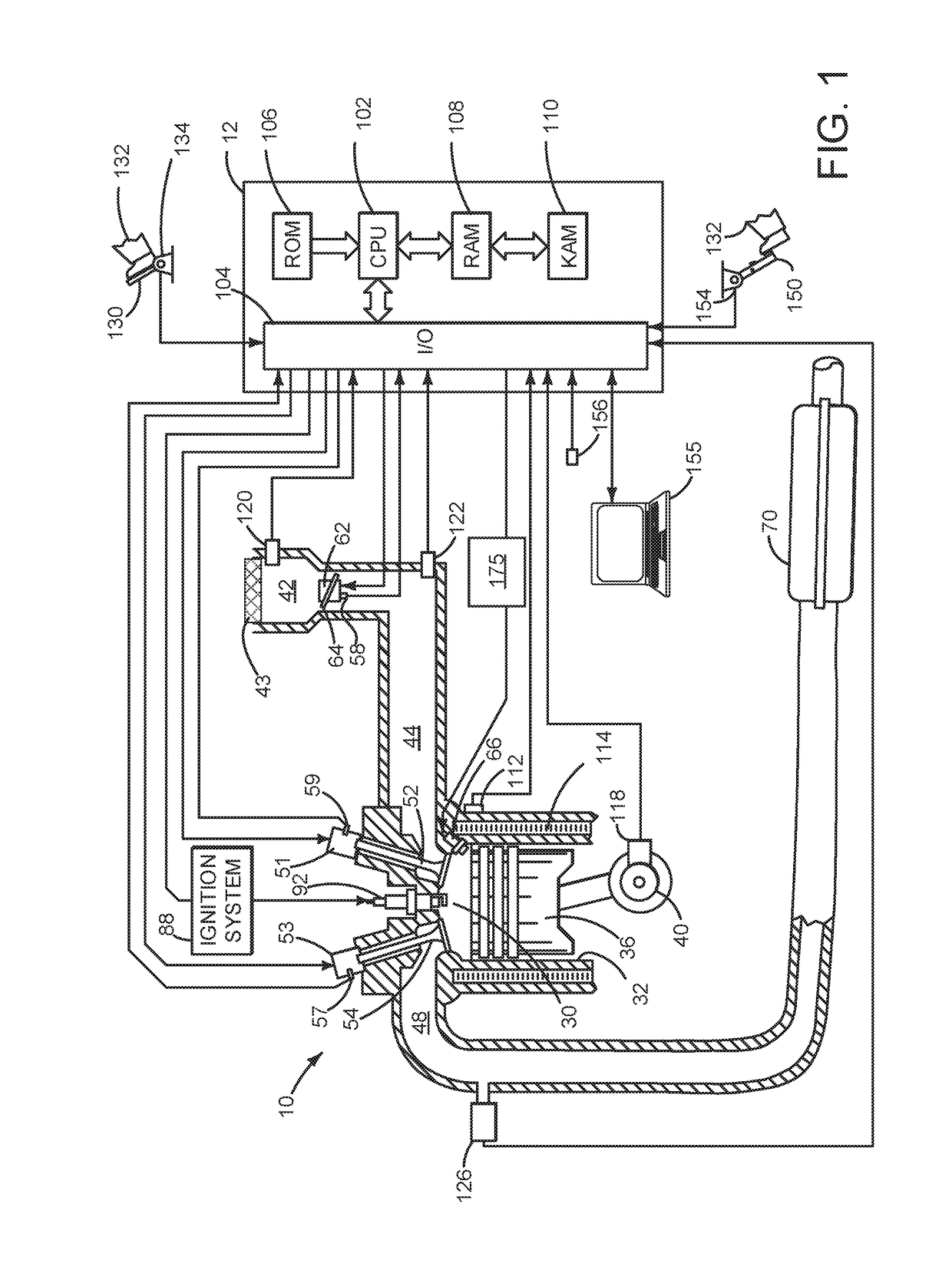
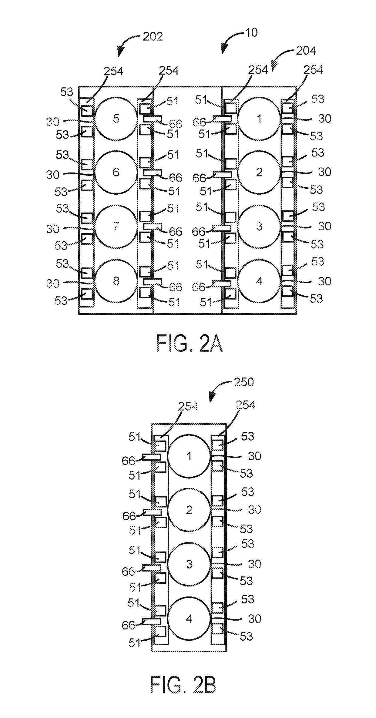
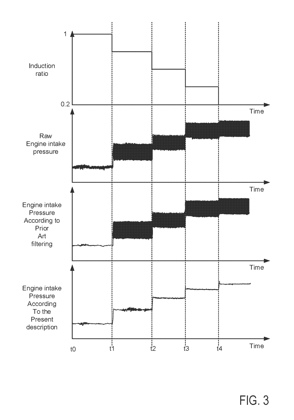
[0016]The present description is related to filtering signals from an engine and controlling the engine responsive to the filtered signals. An engine that includes cylinders that may be selectively deactivated is shown in FIG. 1. FIGS. 2A and 2B show example configurations for the engine described in FIG. 1. FIG. 3 shows an example sequence where engine induction ratio is changed and two different types of filters are applied to signals output from an engine sensor. An example method for processing a signal and controlling an engine responsive to the processed signal is shown in FIG. 4.

[0017]Referring to FIG. 1, internal combustion engine 10, comprising a plurality of cylinders, one cylinder of which is shown in FIG. 1, is controlled by electronic engine controller 12. Engine 10 includes combustion chamber 30 and cylinder walls 32 with piston 36 positioned therein and connected to crankshaft 40.

[0018]Combustion chamber 30 is shown communicating with intake manifold 44 and exhaust ma...


PUM


Abstract

Systems and methods for controlling an engine with cylinders that may be selectively activated and deactivated are presented. In one example, coefficients of a finite impulse response filter are adjusted responsive to changes in engine induction ratio so that undesirable frequencies output from engine sensors may be attenuated to improve engine control.

Description

FIELD[0001]The present description relates to a system and methods for improving operation of an engine that includes cylinders that may be selectively activated and deactivated to conserve fuel while meeting engine torque demands. The system and methods may be applied to an engine that deactivates engine cylinders by deactivating intake and exhaust valves of deactivated cylinders.BACKGROUND AND SUMMARY[0002]An engine control system may sense engine intake manifold pressure to determine engine operating parameters that are a basis for adjusting engine actuators. For example, engine intake manifold pressure may be sampled to determine engine intake manifold absolute pressure (MAP). The engine intake manifold pressure along with engine speed may be converted into an amount of air flowing through the engine using the ideal gas law. Once engine air flow is known, a desired amount of fuel that provides a desired engine air-fuel ratio may be determined by dividing the engine air flow rate...

Claims


Application Information

Patent Timeline
Patent Type & Authority Patents(United States)
IPC IPC(8): F02D41/04F02D41/26F02D41/00
CPCF02D41/0087F02D41/26F02D41/04F02D2041/0012F02D2041/1422F02D2041/1432F02D2041/281F02D2041/286F02D2200/0406
Inventor HELLSTROM, JOHN ERIK MIKAELKARNIK, AMEY YOGESHBANKER, ADAM NATHAN
Owner FORD GLOBAL TECH LLC
Why Eureka
Try Eureka