
Turbomachine rotor blade

a rotor blade and rotor blade technology, applied in the direction of machines/engines, sustainable transportation, climate sustainability, etc., can solve the problems of difficult to avoid overflowing from these portions, difficult to deposit anti-wear material on these portions, aerodynamic losses in the gas flow passage, etc., to improve the mechanical behavior of the blade in operation, facilitate the fabrication of the blade, and improve the ability of the blade to.

Active Publication Date: 2019-02-05
SN DETUDE & DE CONSTR DE MOTEURS DAVIATION S N E C M A
View PDF23 Cites 4 Cited by
  • Summary
  • Abstract
  • Description
  • Claims
  • Application Information

AI Technical Summary

Benefits of technology

This design enhances mechanical behavior, reduces wear, and minimizes overlap by utilizing wipers as contact surfaces, improving vibration damping and static stability while maintaining aerodynamic performance.

Problems solved by technology

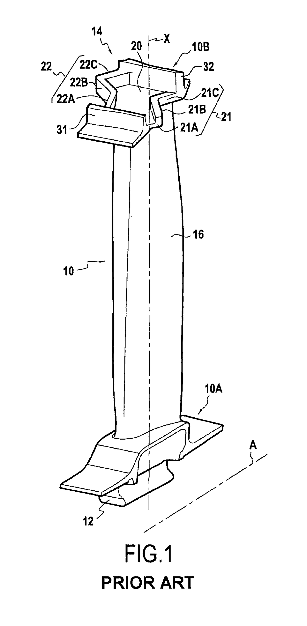
A first problem encountered with such blades 10 stems from the fact that when the second portions 21B, 22B of the outer part 14 are narrow (i.e. present limited height along the stacking axis X), it is difficult to deposit the anti-wear material on these portions 21B, 22B only (i.e. it is difficult to avoid overflowing from these portions), given that the deposition method used is not sufficiently accurate.
Unfortunately, depositing anti-wear material outside the portions 21B, 22B, and in particular on the fillet located between the airfoil 16 and the inside face of the platform 20 is harmful since it may generate cracks in the part and give rise to aerodynamic losses in the gas flow passage.
A solution to that problem consists in “over-dimensioning” the second portions 21B, 22B, i.e. in increasing their height along the stacking axis X. Nevertheless, that solution is not satisfactory since it increases the weight and the size of the outer part 14.

Method used


Image

  • Turbomachine rotor blade
  • Turbomachine rotor blade
  • Turbomachine rotor blade

Examples


Embodiment Construction

[0055]Embodiments of a rotor blade with an outer part are described in detail below with reference to the accompanying drawings. These embodiments illustrate the characteristics and advantages of the invention. It should nevertheless be recalled that the invention is not limited to these embodiments.

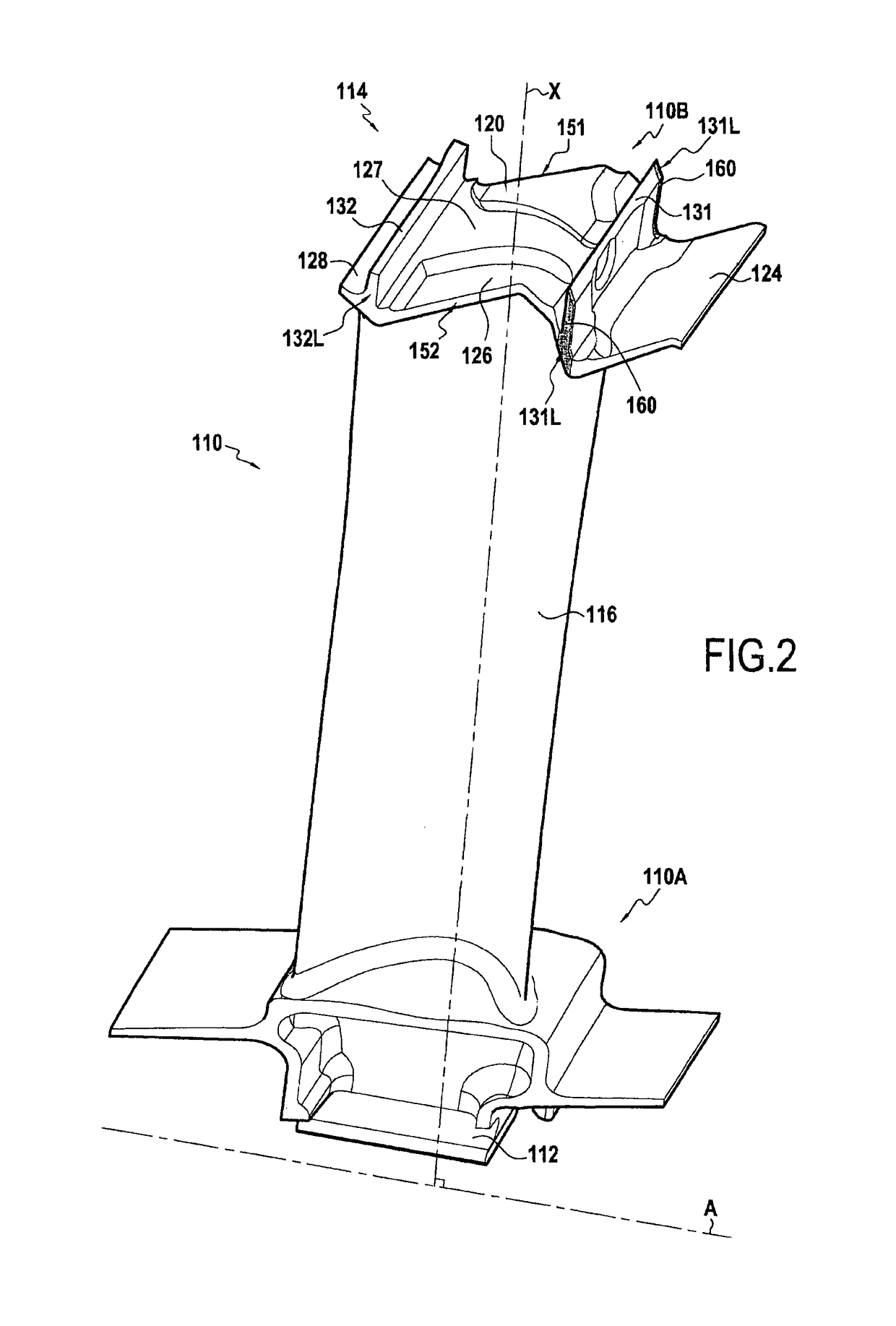
[0056]FIG. 2 shows an embodiment of a turbomachine rotor blade 110. Such a blade may be used in a low pressure stage of an airplane turbojet.

[0057]The rotor blade 110 comprises an airfoil 116 extending along the stacking axis X of the blade between the proximal and distal ends 110A and 110B of the blade (i.e. its inner and outer ends). At its proximal end 110A, the blade has a root 112 whereby it is fastened to a rotor disk (not shown) of a turbomachine (not shown). This disk rotates about the axis A of the engine. At its distal end 110B, the blade 110 has an outer part 114.

[0058]When a plurality of rotor blades 110 are fastened to a rotor disk, their outer parts 114 are arranged side by...


PUM


Abstract

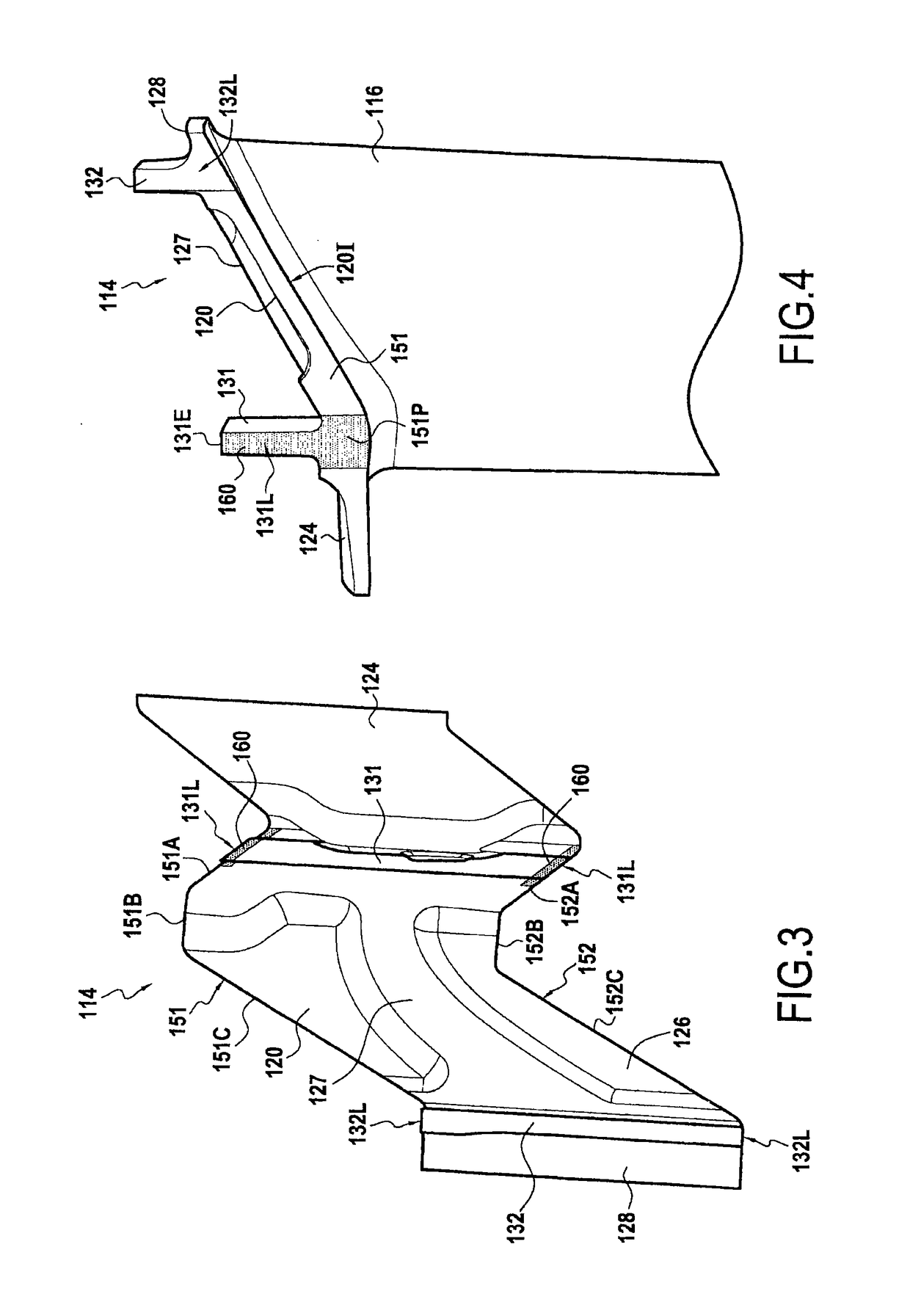
A turbomachine rotor blade includes an outer part at its distal end. The outer part includes a platform defining an outside surface of a passage for gas passing through a turbomachine and presenting first and second opposite side edges; and upstream and downstream sealing wipers extending outwards from the platform, each wiper extending between two lateral faces situated respectively at the first and second side edges. The two lateral faces of the upstream or the downstream wiper are covered at least in part in an anti-wear material.

Description

FIELD OF THE INVENTION[0001]The present description relates to a turbomachine rotor blade.[0002]Such a blade may be fitted to any type of turbomachine whether terrestrial or for aviation, and in particular it may be fitted to an airplane turbojet or to a helicopter turboshaft engine.STATE OF THE PRIOR ART[0003]In the present description, “upstream” and “downstream” are defined relative to the normal flow direction of gas through the turbomachine (from upstream to downstream).[0004]The terms “turbomachine axis” or “engine axis” designate the axis of rotation of the rotor of the turbomachine. The axial direction corresponds to the direction of the axis of the engine and a radial direction is a direction perpendicular to the axis of the engine and intersecting said axis. Likewise, an axial plane is a plane containing the axis of the engine, and a radial plane is a plane perpendicular to said axis.[0005]Unless otherwise specified, the adjectives “inner” and “outer” are used relative to ...

Claims


Application Information

Patent Timeline
Patent Type & Authority Patents(United States)
IPC IPC(8): F01D5/22F01D5/28F01D5/30
CPCF01D5/225F01D5/28F01D5/30F01D5/288Y02T50/673Y02T50/60
Inventor BENSALAH, SLIMNEGRI, ARNAUDDIGARD BROU DE CUISSART, SEBASTIENKLEIN, GUILLAUMETANG, BA-PHUCMATHIEU, DAVIDDOREMUS, SIBYLLE
Owner SN DETUDE & DE CONSTR DE MOTEURS DAVIATION S N E C M A
Learn More