Method and system for boosting the supply of power amplifier

a power amplifier and amplifier technology, applied in multi-frequency code systems, digital transmission, gain control, etc., can solve the problems of wasting more power to respond fast enough, affecting efficiency, and quite substantial power consumption

Active Publication Date: 2019-01-29
FLEISCHER DAVID LEONARDO
View PDF2 Cites 0 Cited by
  • Summary
  • Abstract
  • Description
  • Claims
  • Application Information

AI Technical Summary

Benefits of technology

[0010]According to some embodiments of the present invention, said second circuit is not found in the direct path of said power amplifier and hence is economical in terms of power.

Problems solved by technology

RF PAs are one of the most significant sources of power consumption in these communication systems, and their efficiency has a significant impact on the power supply in these communication systems.
The first type of systems are quite elegant in theory since they eliminate the effect of the high Peak-to-Average Power Ratio (PAPR) altogether, however even in the current very advanced semiconductor processes the amount of computation required to do so, and therefore the power consumption itself is quite substantial; which adversely affects the efficiency they set to improve in the first place.
However, in the prior art some part of the control circuits are also operating linearly and hence waste more power to respond fast enough.
Changing the bias on the fly is also not practical, since linear circuits require time to adjust their linear operation for a changed bias condition; and inserting blank periods between transmitted symbols goes against the intrinsic advantages of orthogonal frequency type of communication systems.

Method used


Image

  • Method and system for boosting the supply of power amplifier
  • Method and system for boosting the supply of power amplifier
  • Method and system for boosting the supply of power amplifier

Examples


Embodiment Construction

[0028]The Figures and the following description relate to preferred embodiments of the present invention by way of illustration only. It should be noted that from the following discussion, alternative embodiments of the structures and methods disclosed herein will be readily recognized as viable alternatives that may be employed without departing from the principles of the claimed invention.

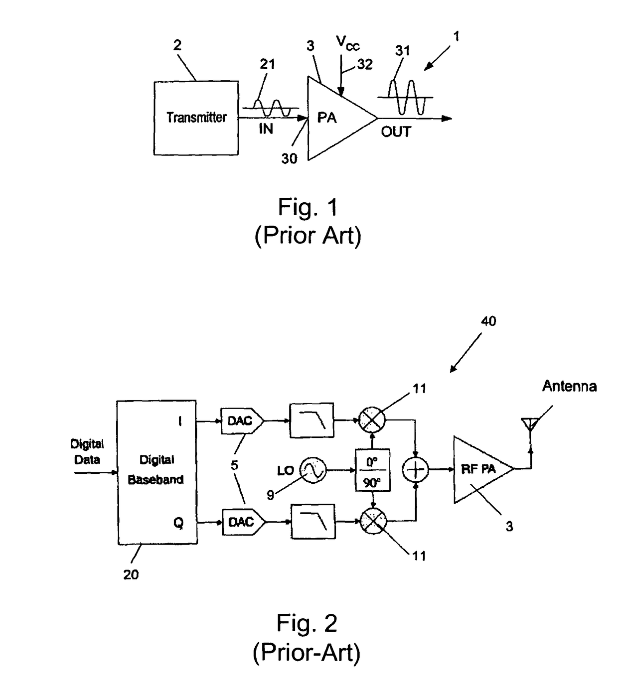
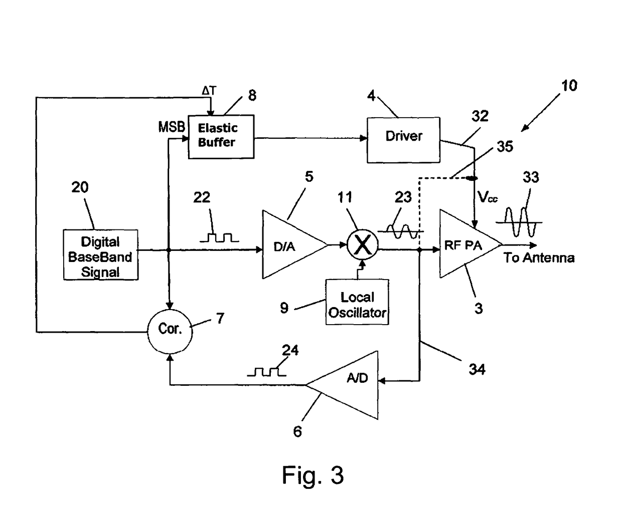
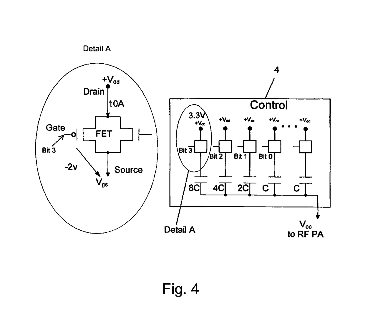
[0029]The present invention provides a conventional amplifier system (e.g., such as the one described with respect to FIG. 1 herein below) with a plurality of capacitors, which can be configured as a charge pump type circuit, to increase the power efficiency of the amplifier system. The charge pump may switch between a fixed input DC voltage and a boosted value for a certain period of time in response to an increase in an input signal to the amplifier. The charge pump may use a switching transistor which is switched on only when the input signal to the amplifier exceeds a threshold. The amplifier...


PUM


Abstract

The present invention relates to a system for boosting the power supply of an RF power amplifier in high peak to average power ratio applications, wherein said power amplifier is coupled to receive and amplify a digital data stream of a baseband signal, (e.g., which after modulation with a carrier wave are supplied as the RF input signal to said power amplifier to generate an RF output signal). Said system comprises: a) a first circuit for controlling said boost by said digital data stream of said baseband signal in open-loop, wherein the timing of said boost event can be adjusted according to delays in the data stream of said system, wherein said boost event is imparted as a copy of the most significant bits of said baseband signal; and b) a second circuit for adjusting the precise timing of said boost event in such a way that the signal which controls said second circuit is the result of a comparison between a digital form of said RF input signal and / or a digital representation of the waveform of said power supply and said digital baseband signal, wherein said comparison represents the substantial matching of the delays in the paths of RF input signal and said power supply.

Description

FIELD OF THE INVENTION[0001]The present invention relates to the field of wireless communications systems characterized by high Peak-to-Average Power Ratio such as OFDM or other Frequency-Division Multiplexing (FDM) scheme used as a digital multi-carrier modulation method. More particularly, the invention relates to a method and system for boosting the supply voltage of the RF amplifier on the fly in order to reduce the power consumption of the system while not affecting significantly the bit error rate.BACKGROUND OF THE INVENTION[0002]Radio Frequency (RF) Power Amplifiers (PA) are widely used in a variety of RF based communication systems and applications such as mobile phones, cellular networks, and other electronic devices. RF power amplifiers are used in these devices to amplify RF signals in order to transmit the RF signals remotely. RF PAs are one of the most significant sources of power consumption in these communication systems, and their efficiency has a significant impact ...

Claims


Application Information

Patent Timeline
Patent Type & Authority Patents(United States)
IPC IPC(8): H03G3/20H03F1/02H03F3/24H04L27/26H03F3/189
CPCH03F1/02H03F1/025H04L27/2614H03F3/24H03F3/189
Inventor FLEISCHER, DAVID LEONARDO
Owner FLEISCHER DAVID LEONARDO
Why Eureka
Try Eureka