Micro-vaporizer heating element and method of vaporization

a technology of heating element and micro-vaporizer, which is applied in the field of resistive heating element for micro-vaporizers, can solve the problems of excessive heat and damage to resistors, and achieve the effects of effective and inexpensive heating element, maximum electrical energy, and low power consumption

Active Publication Date: 2018-01-30
WESTFIELD GROUP
View PDF43 Cites 4 Cited by
  • Summary
  • Abstract
  • Description
  • Claims
  • Application Information

AI Technical Summary

Benefits of technology

[0007]In contrast to conventional wisdom and practice, a conventional resistor is operated above its maximum power rating to function as the heating element for a micro-vaporizer. Operating a resistor above its maximum power rating causes the resistor to heat sufficiently to vaporize a thin film of liquid or solid applied to a surface of the resistor. Operating the resistor above its maximum power rating creates an effective and inexpensive heating element for a micro-vaporizer.
[0008]Damage that might be caused to the resistor by operating it above its maximum power rating is suppressed by cooling the surface of the resistor with a thin film of a vaporizing fluid or solid and by applying electrical energy to the resistor for short periods, such as while a customer repeatedly inhales on a micro-vaporizer. Further, any damage caused to the resistor may be tolerated if the micro-vaporizer is disposed of after a relatively short period of use, such as less than a day, a week or month.
[0009]The embodiments of heating elements for micro-vaporizers disclosed here have benefits including relatively low power consumption, a surface configured to receive and vaporize a thin film of liquid or soluble solid, and may be powered by inexpensive alkaline dry-cell batteries, such as AAA batteries.
[0010]The heating elements for micro-vaporizers disclosed herein may be resistors configured to have a wettable surface and to be used in a micro-vaporizer. These types of heating elements can be beneficial by providing a steep temperature gradient that allows for rapid vaporization; being small and compact heating elements, providing a wettable surface to receive a thin film to be vaporized, and being a single-element that is easily mounted in the micro-vaporizer.

Problems solved by technology

Conventional wisdom is that operating a resistor above its maximum power rating will create excessive heat and damage the resistor.

Method used


Image

  • Micro-vaporizer heating element and method of vaporization
  • Micro-vaporizer heating element and method of vaporization
  • Micro-vaporizer heating element and method of vaporization

Examples


Embodiment Construction

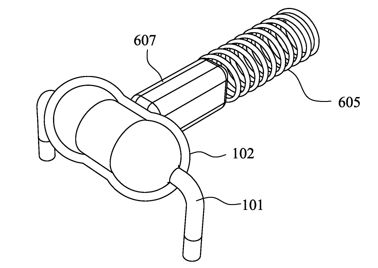
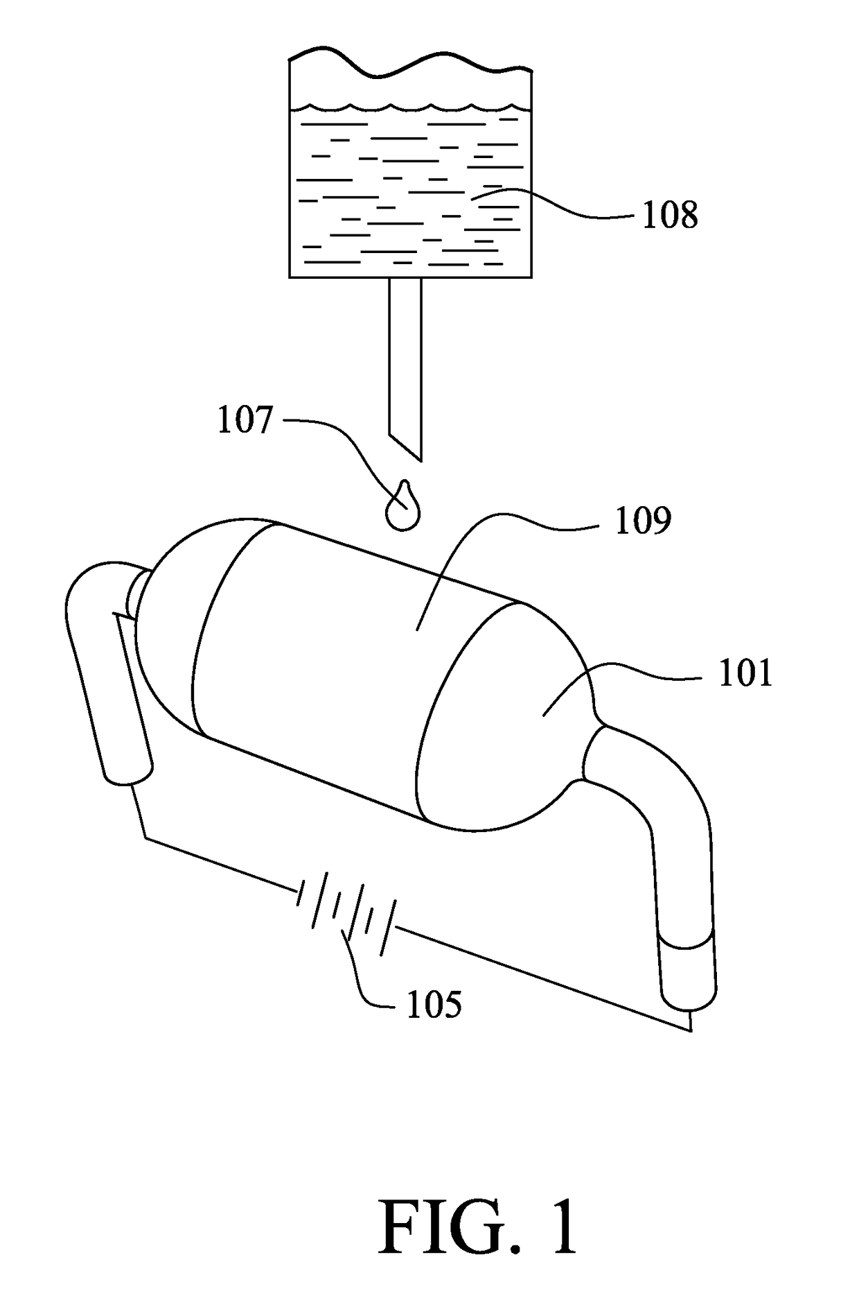
[0022]FIG. 1 illustrates a micro-vaporizer equipped with a single-structured heating element 101, such as a standard resistor with a low power rating. The heating element 101 includes a wettable surface 109 that is adapted to be coated with a thin film of a fluid or soluble solid. The wettable surface may be on the outer surface of the heating element and may have a cylindrical shape.

[0023]The wettable surface 109 may be formed of a plastic material commonly used to form the casing for electrical resistors. The wettable surface may have a texture, e.g., smooth, knurled, roughened or with capillary grooves, to promote distribution of a thin film on the surface. The wettable surface may be coated, e.g., painted, with a material that does not mix with the fluid or soluble solid. The wettable surface may hygroscopic to adsorb a liquid. For example, the wettable surface may be formed of polymers such as any or allow of nylon, ABS, polycarbonate, cellulose, poly(methyl methacrylate), poly...


PUM


Abstract

A heating element for a micro-vaporizer including a heating element, and a wetted surface or a fluid storing membrane that fit snuggly onto an outer surface of the heating element. Vaporization is achieved by applying a current through the heating element that is higher than an inherent power rating of the heating element to generate heat that vaporizes fluids supplied to the wetted surface or stored in the fluid storing membrane.

Description

TECHNICAL FIELD[0001]The invention disclosed herein relates generally to micro-vaporizers that heat a liquid to generate vapor. The invention particularly relates to resistive heating elements for micro-vaporizers.BACKGROUND OF THE DISCLOSURE[0002]Micro-vaporizers heat and vaporize small amounts of liquids or soluble solids, such as nicotine containing liquids, fragrances, flavored liquids, chemical agents, biochemical agents, essences, glues, waxes, resins, and saps. Micro-vaporizers typically vaporize fluids at a rate of less than 100 milliliters per hour (ml / h). Micro-vaporizers are applied in products such as: electronic cigarettes, home fragrance dispensers, personal and home dispensers of bug repellent, and medical treatment dispensers for inhalers. Micro-vaporizers are often applied in consumer products used by retail consumers with little or no training or instruction in the use of the product. Micro-vaporizers should be safe for consumer use, easy to operate, reliable, deli...

Claims


Application Information

Patent Timeline
Patent Type & Authority Patents(United States)
IPC IPC(8): A61M16/00A24F47/00A24F40/10A24F40/20A24F40/46
CPCA24F47/008A24F40/10A24F40/46
Inventor DAI, WEIXU, YONGJIE JAMES
Owner WESTFIELD GROUP
Why Eureka
Try Eureka