
Head unit having nozzle chips arranged side by side and liquid jetting apparatus including the same

a technology of nozzle chips and liquid jetting apparatus, which is applied in the direction of printing, inking apparatus, etc., can solve the problems of difficult to suppress the above-described variation to be small only with the adhesive, and achieve the effect of suppressing any variation in height and increasing the distance between the nozzle chips

Active Publication Date: 2019-01-29
BROTHER KOGYO KK
View PDF5 Cites 1 Cited by
  • Summary
  • Abstract
  • Description
  • Claims
  • Application Information

AI Technical Summary

Benefits of technology

This configuration effectively suppresses variations in nozzle chip heights, allowing for closer arrangement of nozzle chips while maintaining precise flatness and ensuring adequate overlapping for improved image quality.

Problems solved by technology

In reality, however, it is difficult to suppress the above-described variation to be small only with the adhesive.
However, in a case that an attempt is made to apply the technique of the latter line-type jetting head to the configuration of the former line-type jetting head, the following problem might occur.

Method used


Image

  • Head unit having nozzle chips arranged side by side and liquid jetting apparatus including the same
  • Head unit having nozzle chips arranged side by side and liquid jetting apparatus including the same
  • Head unit having nozzle chips arranged side by side and liquid jetting apparatus including the same

Examples


modification 1

[0083][Modification 1]

[0084]It is allowable that, as in a head unit 11A depicted in FIG. 7, two projections 31A are arranged to face each other in the chip longitudinal direction such that each of the nozzle chips 12 is sandwiched therebetween. With this, the pressing manner by which the first projections 31 press the fixing plate 13 becomes uniform on the both sides in the chip longitudinal direction, thereby making it possible to reduce the variation in height of the fixing plate 13 to be small. Further, as depicted in FIG. 7, in a case that the two first projections 31A are arranged on a straight line extending in the chip longitudinal direction and passing through the plurality of nozzles 15, it is possible to reduce the variation in height of the fixing plate 13 on the both sides in the chip longitudinal direction to be further small.

modification 2

[0085][Modification 2]

[0086]In the embodiment, two pieces of the second projection 32 arranged on the both sides of a nozzle chip 12 face each other in the chip short direction. It is allowable, however, that two pieces of second projections 32B on the both sides of each of the nozzle chips 12 face each other in the left / right direction, as in a head unit 11B depicted in FIG. 8. Namely, it is allowable that the positions of two second projections 32B, which are arranged on both the left and right sides of one piece of the nozzle chips 12, are coincident in the front / rear direction.

modification 3

[0087][Modification 3]

[0088]It is allowable that two or more pieces of a first projection 31C may be arranged along each of end surfaces 12a of the end portions in the longitudinal direction of each of the nozzle chips 12, as in a head unit 11C depicted in FIG. 9. In this configuration, it is possible to determine the height position of the fixing plate 13 assuredly in the vicinity of the end surfaces 12a of each of the nozzle chip 12.


PUM


Abstract

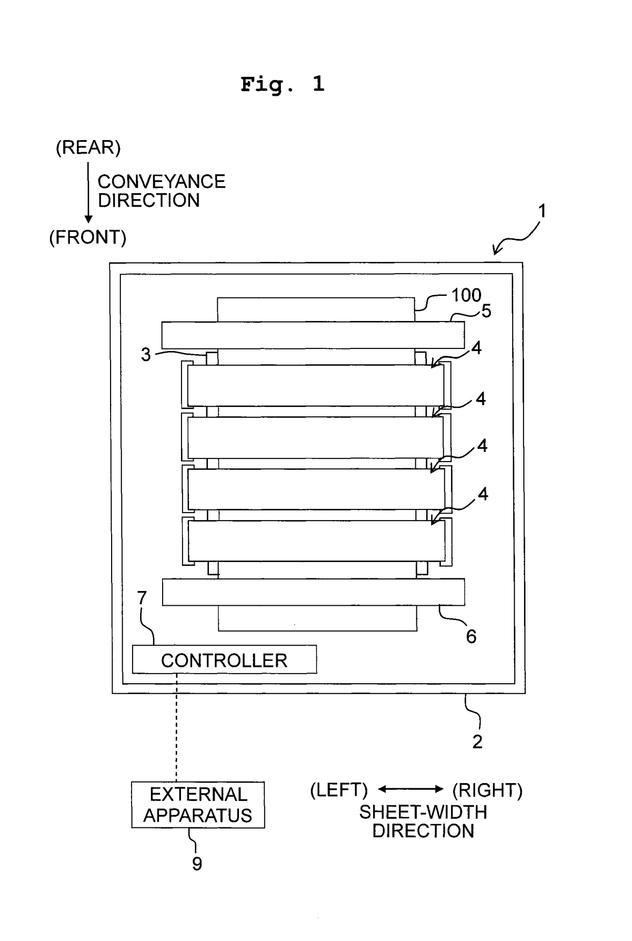
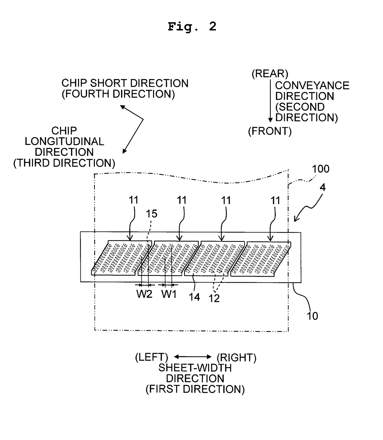
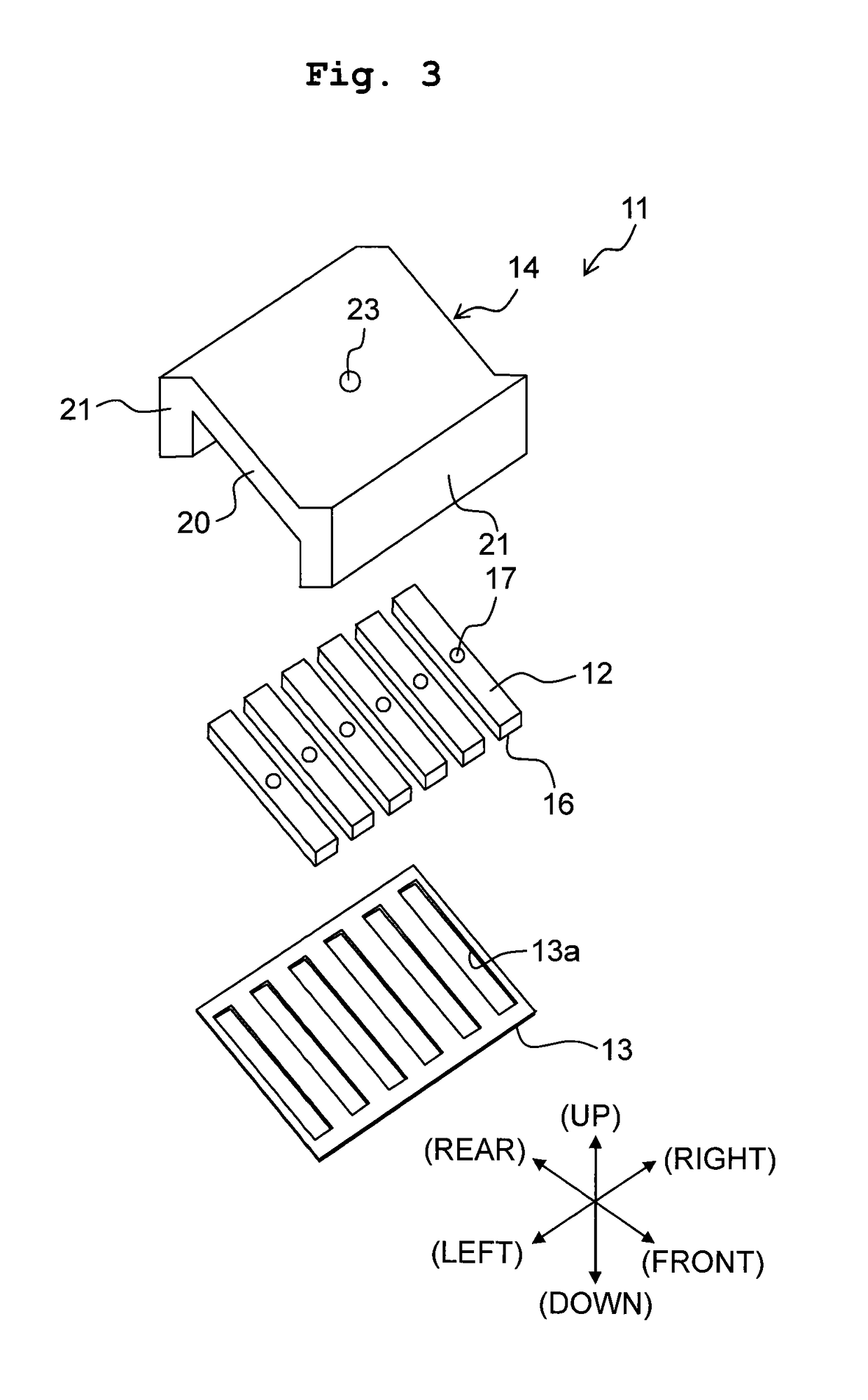
A head unit includes: nozzle chips which are arranged side by side in a first direction, each of the nozzle chips having a jetting surface and nozzles aligned in a predetermined direction parallel to the jetting surface and crossing both of the first direction and a second direction orthogonal to the first direction; a holder configured to hold the nozzle chips from a side opposite to the jetting surface; and a fixing plate to which the nozzle chips are fixed and which is arranged on a side facing the jetting surface of each of the nozzle chips, wherein the holder has first walls arranged in the second direction so as to sandwich the nozzle chips therebetween; each of the first walls has first projections formed on an end surface thereof facing the fixing plate; and the first projections make contact with the fixing plate.

Description

CROSS REFERENCE TO RELATED APPLICATION[0001]The present application claims priority from Japanese Patent Application No. 2016-070943 filed on Mar. 31, 2016 the disclosure of which is incorporated herein by reference in its entirety.BACKGROUNDField of the Invention[0002]The present invention relates to a head unit, and a liquid jetting apparatus provided with a plurality of head units.Description of the Related Art[0003]Conventionally, there is known a line-type jetting head, as the liquid jetting apparatus, having a configuration wherein a plurality of head units (ink-jet recording heads) are arranged side by side in the width direction of a recording medium.[0004]In such a line-type jetting head, each of the head units has a plurality of nozzle chips (head bodies) which are arranged side by side in the width direction of the recording medium, a holding member holding the plurality of nozzle chips, and a fixing plate arranged on a side of jetting surfaces of the plurality of nozzle ...

Claims


Application Information

Patent Timeline
Patent Type & Authority Patents(United States)
IPC IPC(8): B41J2/21B41J2/145
CPCB41J2/2146B41J2/145B41J2202/20B41J2202/19B41J2/155
Inventor HAYASHI, HIDEKISUGIURA, KEITAMIZUNO, TAISUKE
Owner BROTHER KOGYO KK
Learn More