
Connector system with adapter

a technology of connectors and adapters, applied in the direction of fixed connections, coupling device connections, printed circuit aspects, etc., can solve the problems of insufficient stacked connectors, insufficient stacked connectors, and difficulty in attempting to stack three ports vertically, and achieve the effect of increasing the density of ports

Active Publication Date: 2019-01-22
MOLEX INC
View PDF14 Cites 4 Cited by
  • Summary
  • Abstract
  • Description
  • Claims
  • Application Information

AI Technical Summary

Benefits of technology

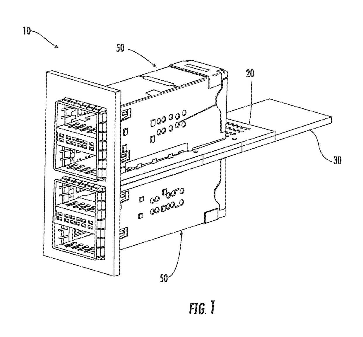
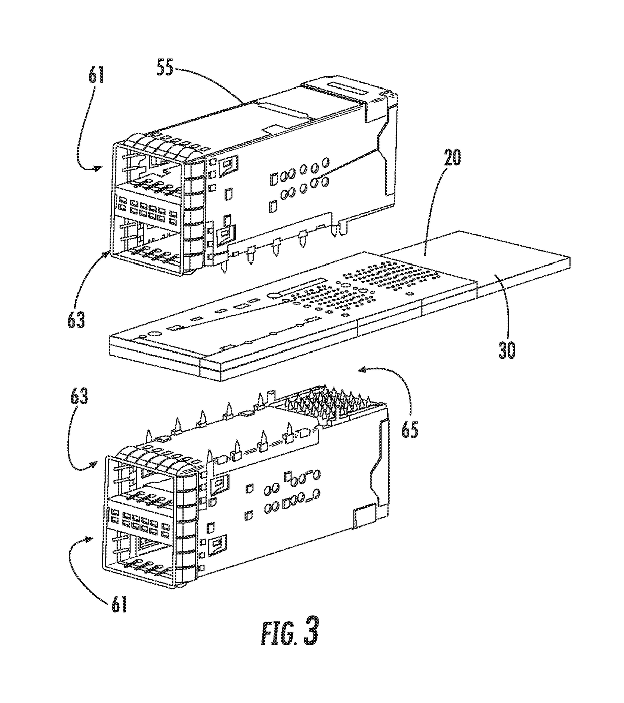
This patent is about a connector system that allows for high port density and the reuse of existing tooling. The system includes a main board with two connectors mounted on opposite sides in a belly-to-belly arrangement. The connectors engage vias on the main board. An interposer board is positioned between the main board and includes vias that engage the tails of the second connector. The interposer board also has double tails that provide an electrical connection between vias on the main board. The system allows for increased port density and efficient use of existing tooling.

Problems solved by technology

One issue that exists with current switches and servers is the need for additional bandwidth per front face area.
While stacked connectors help provide additional port density, for certain applications stacked connectors are insufficient.
Attempting to stack three ports vertically is problematic from a manufacturing standpoint.
A belly-to-belly solution works fairly well with single ports that can be surface mount (SMT) attached but SMT attachment introduces process limitations and thus some individuals would prefer to press-fit their connectors into the circuit board.
While it is possible to press-fit two connectors to opposing sides of a circuit board, providing belly to belly designs requires either a very thick motherboard (which often would be cost prohibitive) or unique footprints / routing configurations that are difficult to ensure support high data rates.
Attempting to increase the data rate is also difficult, especially as data rates reach 25 Gbps per transmit / receive channel as circuit boards become increasing lossy as high frequencies.

Method used


Image

  • Connector system with adapter
  • Connector system with adapter
  • Connector system with adapter

Examples


Embodiment Construction

[0017]The detailed description that follows describes exemplary embodiments and is not intended to be limited to the expressly disclosed combination(s). Therefore, unless otherwise noted, features disclosed herein may be combined together to form additional combinations that were not otherwise shown for purposes of brevity.

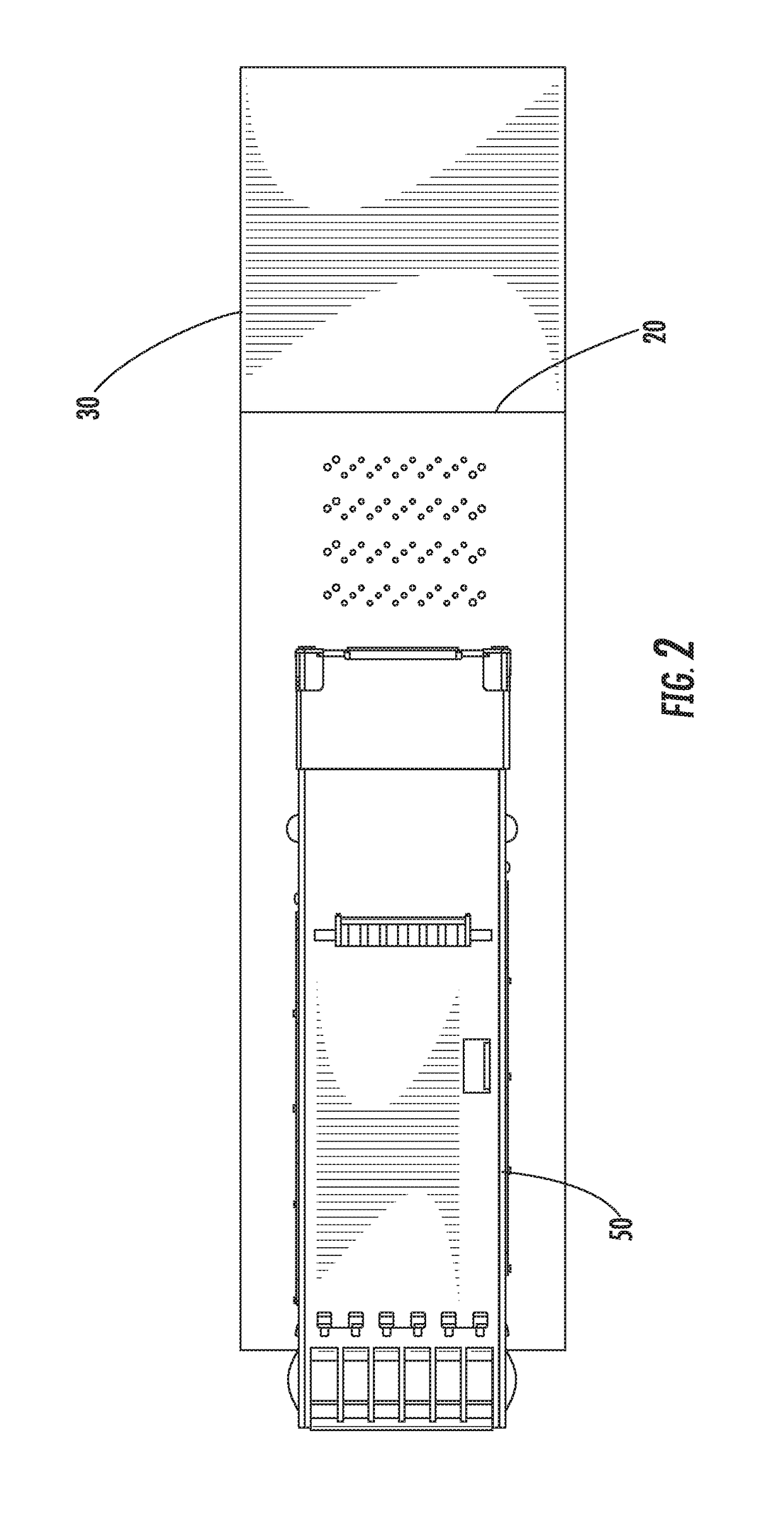
[0018]As can be appreciated from the Figs., a connector system 10 includes a main board 30 with a first side 31a and a second side 31b and the main board 30 can be formed of conventional circuit board material or that can use other additive processes. The main board 30 supports a first stacked connector 50 and can further support a second stacked connector 50, where the first and second stacked connectors are in a belly-to-belly configuration. To provide room for the footprint, an interposer board 20 is mounted on the main board 30. Because the interposer board 20 provides vias to connect to the second connector 50, both the first and second connectors 50 can have...


PUM


Abstract

A connector system includes a main board and an interposer board. The main board and the interposer board are each configured to mate to a separate connector and are connected together by vias. The vias can provide an electrical path from the interposer board to the main circuit board so that a first connector mounted on the interposer board can be positioned directly in line with a second connector mounted on the main circuit board. The interposer helps make the routing out of signal traces from the two connector simpler while reducing the need for additional layers on the main board. Two connectors can be press-fit mounted to the main board and the interposer board in a belly-to-belly configuration.

Description

RELATED APPLICATIONS[0001]This application is a national stage of International Application No. PCT / US2016 / 053716, filed Sep. 26, 2016, which claims priority to U.S. Provisional Application No. 62 / 232,660, filed Sep. 25, 2015, both of which are incorporated herein by reference in their entirety.TECHNICAL FIELD[0002]This disclosure relates to field of input / output (IO) connectors, more specifically to IO connectors in stacked configurations.DESCRIPTION OF RELATED ART[0003]IO connectors are frequently used to in server and switch applications. One issue that exists with current switches and servers is the need for additional bandwidth per front face area. While stacked connectors help provide additional port density, for certain applications stacked connectors are insufficient. Attempting to stack three ports vertically is problematic from a manufacturing standpoint. One attempt to address this problem is to provide a belly to belly design, which involves mounting two connector to the...

Claims


Application Information

Patent Timeline
Patent Type & Authority Patents(United States)
IPC IPC(8): H01R12/00H05K1/14H01R13/518H01R13/6583H01R12/58H01R12/72
CPCH01R12/722H01R12/585H01R13/518H05K1/144H01R13/6583H05K2201/10189H05K2201/041
Inventor REGNIER, KENT E.
Owner MOLEX INC
Learn More