Forced air battery charging system

a battery charging and air force technology, applied in the direction of renewable energy generation, machines/engines, propulsion parts, etc., can solve the problems of minimal efficiency and economic inability to generate electricity, and achieve the effect of maximizing air reception and maximizing electricity generation efficiency

Inactive Publication Date: 2019-01-08
BIRD BRETT W
View PDF12 Cites 8 Cited by
  • Summary
  • Abstract
  • Description
  • Claims
  • Application Information

AI Technical Summary

Benefits of technology

This patent is about a system for charging batteries using air. The system is designed to maximize air intake and prevent leaks, which helps to generate electricity more efficiently. It also includes an air duct that directs air under the automobile to prevent drag.

Problems solved by technology

Although presumably effective for their intended purposes, such systems and proposals have been fraught with inefficiencies so pronounced as to make the electricity generation of minimal efficacy and economically unfeasible.

Method used


Image

  • Forced air battery charging system
  • Forced air battery charging system
  • Forced air battery charging system

Examples


Embodiment Construction

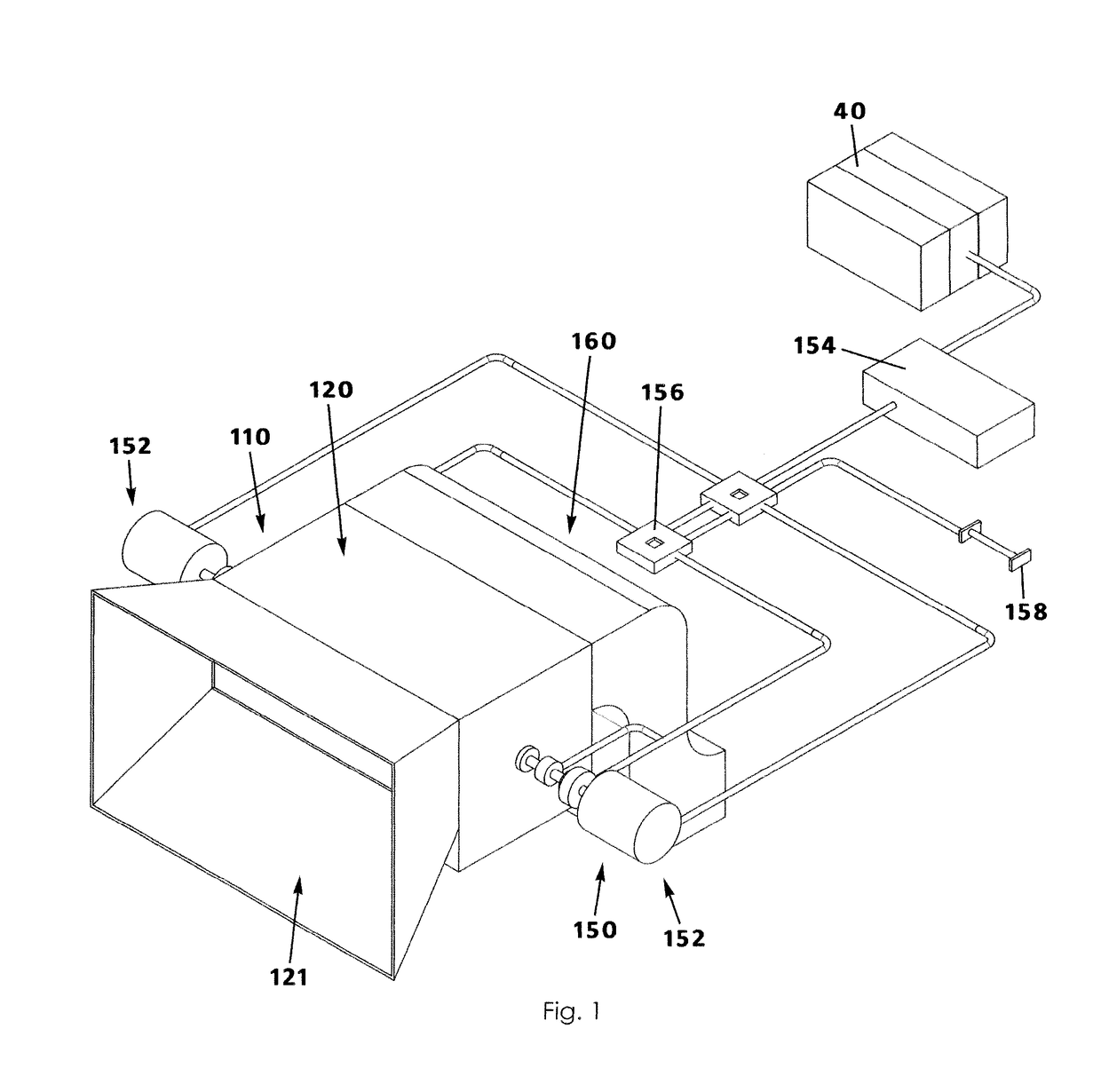
[0022]A forced-air battery charging system for operation in a vehicle and vehicles having such systems will now be described in details with reference to FIGS. 1 to 11b of the accompanying drawings. A vehicle 10 (FIGS. 11a and 11b) includes an engine compartment 20, a passenger area 30, a battery 40, a plurality of wheels 50 for moving the engine compartment 20 and the passenger area 30, and a forced-air battery charging system 100. The engine compartment 20 may generally be positioned forward of the passenger area 30.

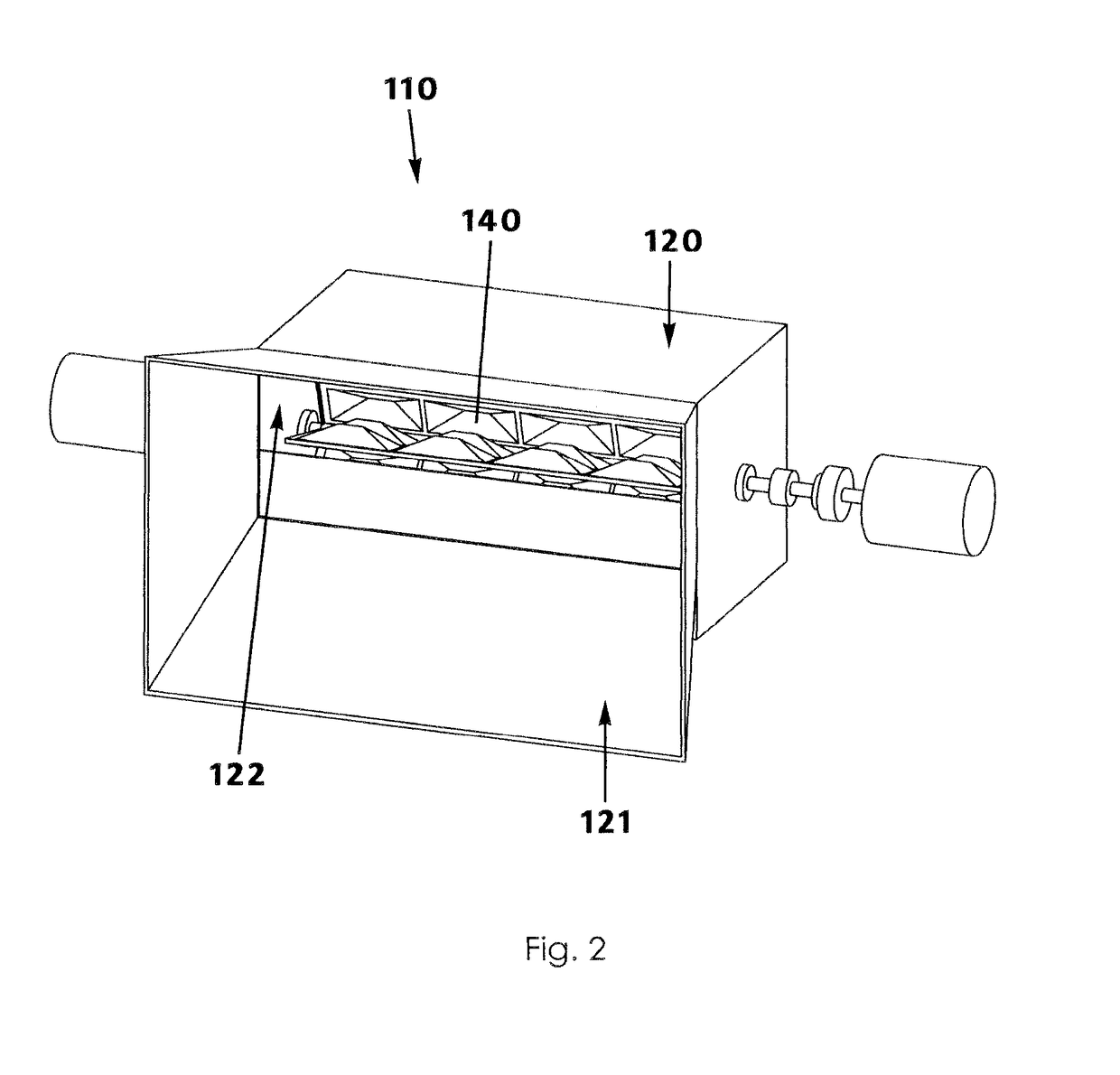
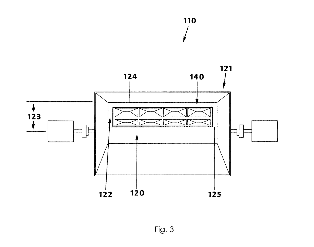
[0023]The forced air battery charging system 100 includes a turbine assembly 110 having a casing 120 and a plurality of blades 140, an electricity generator 150 operatively coupled to the plurality of blades 140, and an air duct 160. The casing 120 is positioned in the engine compartment 20 and has an inlet 122 operably receiving ambient air A1 (FIG. 11b) as the vehicle 10 travels forwardly and an outlet 126 operably expelling the ambient air A1. The plurality of blade...


PUM


Abstract

A forced-air battery charging system for a vehicle having an engine compartment includes a turbine assembly having a casing and a plurality of blades, the casing being positioned forwardly in the engine compartment for operably receiving ambient air as the vehicle travels forwardly and having an outlet expelling the ambient air. The plurality of blades are situated in the casing between the inlet and the outlet and are operable to rotate about an axis when impacted by the received ambient air in a direction askew to the axis. An electricity generator is operatively coupled to the plurality of blades. The system includes an air duct having walls that define a channel having proximal and distal ends, the proximal end being open and in communication with the casing outlet, the distal end being open through which the ambient air exits under the vehicle after passing through the air duct proximal end.

Description

BACKGROUND OF THE INVENTION[0001]This invention relates generally to electricity generation systems and, more particularly, to a battery charging system installed behind the grill of an automobile and configured to receive an air stream through the grill when the automobile is moving forward (i.e. when driving) and operating a high efficiency electrical generator for charging a battery or other electrical systems of the automobile.[0002]With the popularity and importance of electric vehicles, strategies for charging and recharging the vehicle battery or otherwise powering the vehicle are important to consider. Electric car batteries are typically recharged using a home charging plug-in unit, such as a 7 kW home unit. Recharging may take from 30 minutes to 12 hours depending on the size of the battery and recharging apparatus. More recently, there have been attempts to charge an electric vehicle battery using incoming air during forward motion of the car. Although presumably effectiv...

Claims


Application Information

Patent Timeline
Patent Type & Authority Patents(United States)
IPC IPC(8): B60L8/00H02K11/00H02K11/04H02K7/11B60K16/00F03D3/00F03D3/06F03D9/11F03D9/25F03D9/32F03D3/04H02K7/18
CPCB60L8/006B60L11/1809F03D3/002F03D3/061F03D9/11F03D9/25F03D9/32F03D3/0427H02K7/183H02K11/0094H02K11/046H02K7/11B60K16/00F05B2250/5011B60K2016/006F05B2220/31F05B2220/7068F05B2240/30F05B2240/221F05B2240/941B60K1/00B60L53/00Y02E10/728Y02E10/74Y02T10/90Y02T90/16Y02T10/70Y02T90/14Y02T10/7072Y02E70/30H02K11/05
Inventor BIRD, BRETT W.
Owner BIRD BRETT W
Why Eureka
Try Eureka