
Battery mounting device for an electric all terrain vehicle or an electric utility vehicle

Inactive Publication Date: 2019-01-08
HUANG CHIEN HSIANG
View PDF6 Cites 5 Cited by
  • Summary
  • Abstract
  • Description
  • Claims
  • Application Information

AI Technical Summary

Benefits of technology

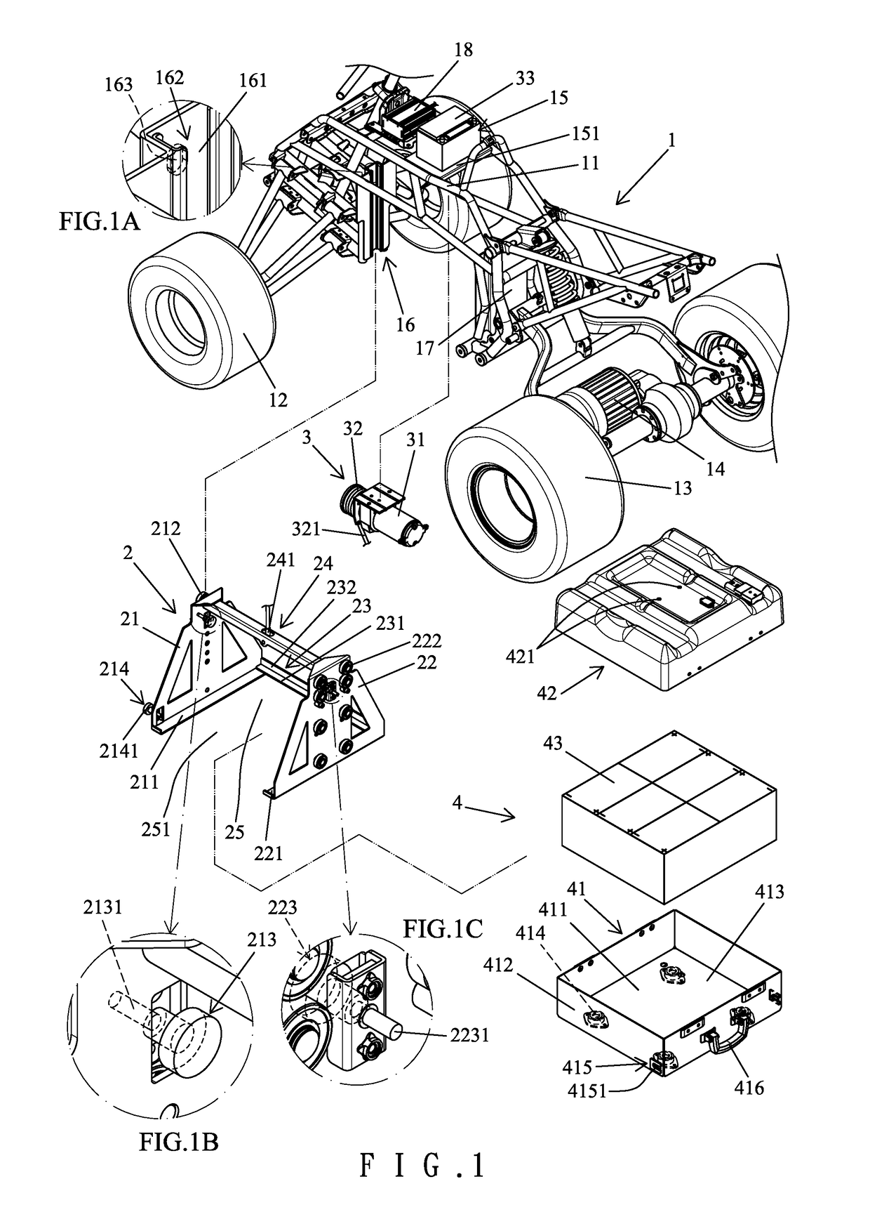
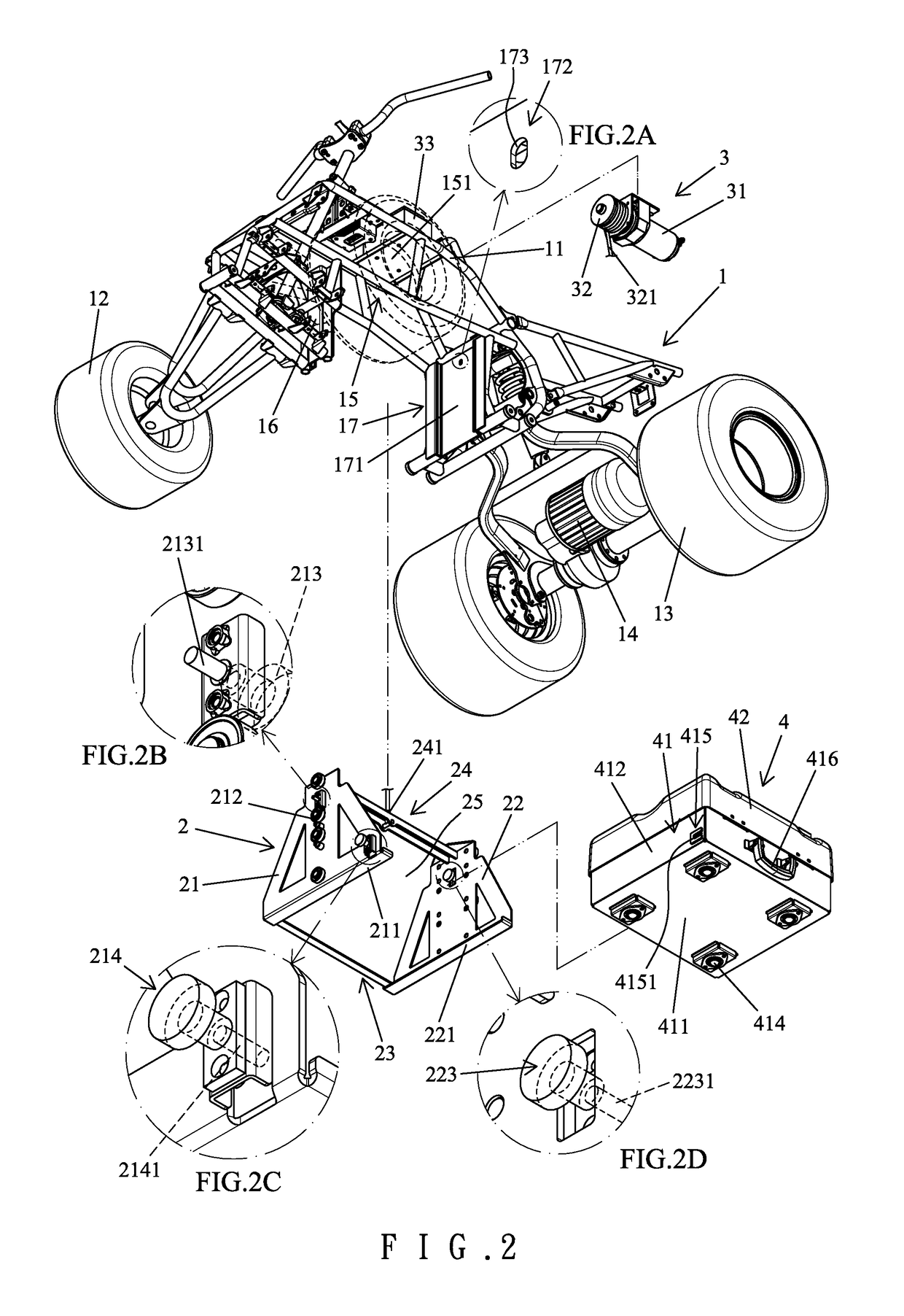
The present invention aims to provide a battery mounting device that makes replacing batteries and ensuring stable mounting easier.

Problems solved by technology

However, charging batteries requires several hours during which the electric vehicle cannot move.
A vehicle having a larger volume has more batteries which are heavier and which are not easy to be rapidly replaced by a user or a repairman.

Method used


Image

  • Battery mounting device for an electric all terrain vehicle or an electric utility vehicle
  • Battery mounting device for an electric all terrain vehicle or an electric utility vehicle
  • Battery mounting device for an electric all terrain vehicle or an electric utility vehicle

Examples


Embodiment Construction

[0025]With reference to FIGS. 1-4, a battery mounting device according to the present invention includes a body 1, an elevating seat 2, an actuation device 3, and a battery seat 4. The body 1 can be of a type of an all terrain vehicle, an utility vehicle, or other vehicle. The body 1 includes a frame 11, two front wheels 12 mounted to a front end of the frame 11, and two rear wheels 13 mounted to a rear end of the frame 11. A power motor 14 is mounted to the rear end of the frame 11 to drive the rear wheels 13 to rotate. The frame 11 includes a connecting portion 15 having an upper connecting board 151 extending parallel to the ground. The connecting portion 15 further includes a front guiding board 16 at a front end thereof and a rear guiding board 17 at a rear end thereof. Each of the front guiding board 16 and the rear guiding board 17 extends in a vertical direction perpendicular to the ground. The front guiding board 16 includes a rear side having a front guiding groove 161 ext...


PUM


Abstract

A battery mounting device includes a body having a frame with a connecting portion. The connecting portion includes at least one positioning portion. An elevating seat is mounted to the frame and is movable between a mounting position and a replacement position lower than the mounting position. The elevating seat includes at least one positioning member disengageably coupled to the at least one positioning portion. An actuation device is mounted to the frame and is operable to move the elevating seat in the vertical direction. A battery seat is detachably mounted to the elevating seat and includes a lower positioning portion coupled with a lower positioning member of the elevating seat in the mounting position. When the elevating seat is in the replacement position, the battery seat is placed on the ground, and the lower positioning portion is disengaged from the lower positioning member.

Description

BACKGROUND OF THE INVENTION[0001]The present invention relates to a battery mounting device for an electric all terrain vehicle or an electric utility vehicle and, more particularly, to a battery mounting device providing easier replacement and improved mounting stability.[0002]In view of the serious problems of global warming and air pollution, energy saving and reduction of carbon emission are important issues in many countries. Thus, electric vehicles free of internal combustions do not directly discharge waste gases and are, thus, the current design trend of vehicles.[0003]An electric vehicle includes a motor as a driving source. The electric vehicle must include one or more batteries according to the size of the electric vehicle to enable the motor to operate a predetermined period of time. Batteries having insufficient electricity must be recharged to permit the motor to operate again.[0004]However, charging batteries requires several hours during which the electric vehicle ca...

Claims


Application Information

Patent Timeline
IPC IPC(8): B60K1/04
CPCB60K1/04B60L11/1877B60K2001/0422B60L50/66B60K2001/0405B60K2001/0472B60Y2200/12Y02T10/70
Inventor HUANG, CHIEN-HSIANG
Owner HUANG CHIEN HSIANG
Learn More