Device and method for transmitting data

a technology of transmitting device and data, applied in the direction of transmission/receiver shaping network, modulated carrier system, power amplifier, etc., can solve the problems of increasing the cost of a respective filter, and the method practically cannot be realized, so as to reduce and the interference between signals transmitted in different transmission or communication channels

Active Publication Date: 2018-12-25
UNIVET DER BUNDESWEHR MUENCHEN
View PDF6 Cites 0 Cited by
  • Summary
  • Abstract
  • Description
  • Claims
  • Application Information

AI Technical Summary

Benefits of technology

[0010]It is therefore an object of the invention to provide a method for the transmission of data using frequency multiplexing, wherein interferences between signals transmitted in different transmission or communication channels are decreased. It is also an object of the invention to provide a data transmission device for transmitting data using frequency multiplexing, wherein interferences between signals transmitted in different transmission or communication channels are decreased.
[0014]In case the modulated carrier signal as such already comprises frequency components outside the used transmission channel, which is, for example, given with CPM-signals, a filter also could be placed upstream of the power amplifier. However, a signal passing the filter will loss its constant envelope waveform and the power amplifier due to its non-linear characteristics will reconstruct the frequency components outside the used channel. Accordingly, the effect of a filter placed upstream of a power amplifier is lost. When, on the other hand, the amplification of the power amplifier is decreased, the advantage of high efficient transmission methods using signals with a constant envelope waveform is lost.
[0019]According to an embodiment of the invention, the elimination of the undesired frequency components takes place downstream of the power amplifier. Therefore, a constant envelope waveform of a signal to be transmitted is not changed before amplification. Hence, a power amplifier with high non-linear distortions can be used and a large efficiency in amplification is reached. The described compensation method compared to a direct filtering of the amplified signal is also more cost-effective due to the fact that a low-loss filter with a narrow bandwidth suitable for high carrier frequencies is difficult to realize. The compensation method according to the invention has the further advantage, that no undesired spectral components are transmitted. Large differences in the amplitudes of signals transmitted in adjoint channels make no problem.
[0026]In an embodiment the compensated transmission signal along a feedback path can be compared with the compensation signal or with the filtered signal and at least one of a phase, an amplitude and a delay of the compensation signal is adapted based on the comparison result. With the comparison of the transmission signal to the compensation signal or to the filtered signal an adaptive modification of the phase, the amplitude and / or the delay of the compensation signal can easily be achieved to reach an effective compensation of the undesired frequency components outside the used transmission channel particularly with signal parameters varying in time.

Problems solved by technology

However, this method practically cannot be realized due to the large ratio of the carrier frequency to the band width of the transmission channel in state of the art radio communication systems.
This cannot be easily achieved in case of a large ratio of the carrier frequency to the channel band width, which increases the costs of a respective filter.

Method used


Image

  • Device and method for transmitting data
  • Device and method for transmitting data
  • Device and method for transmitting data

Examples


Embodiment Construction

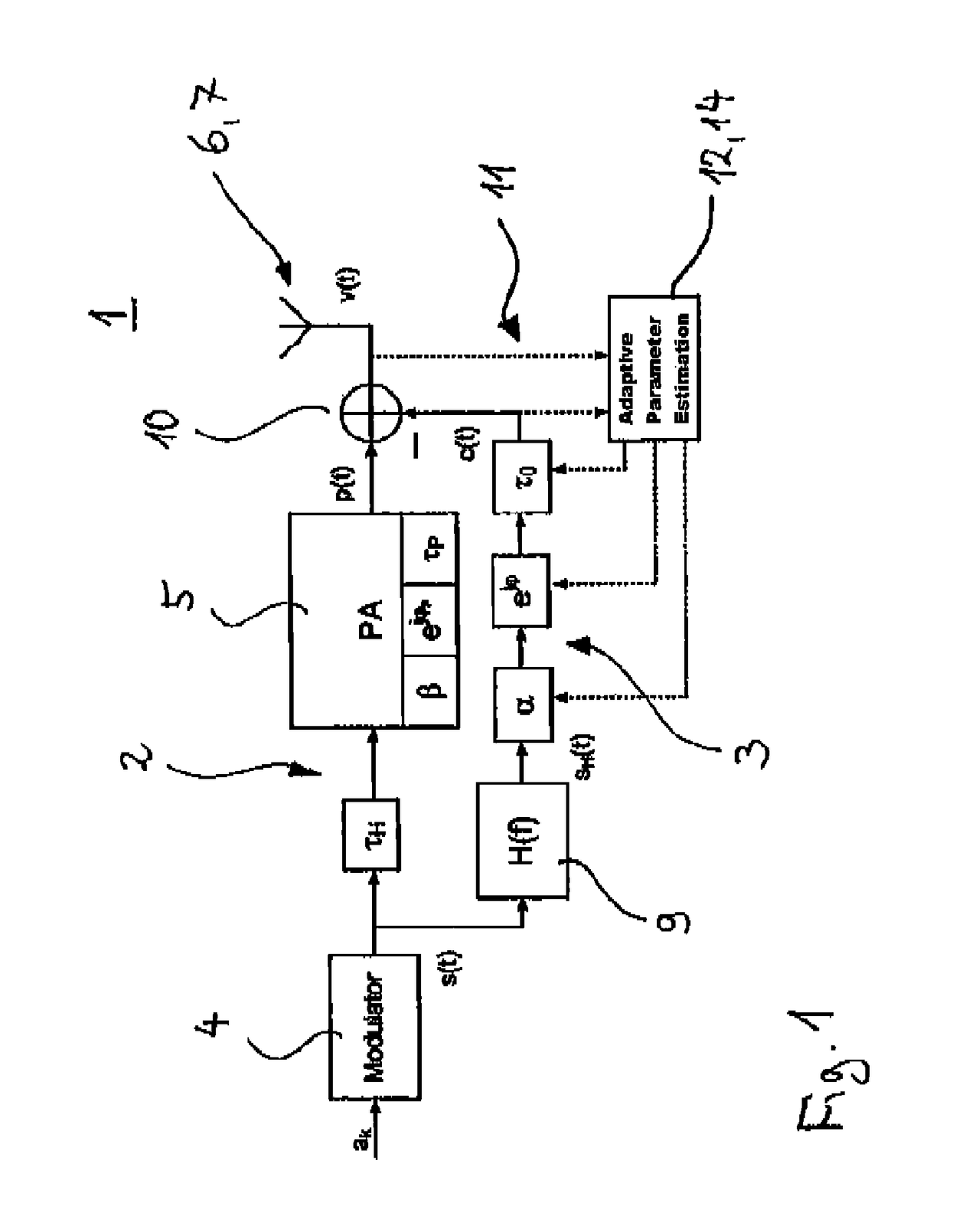
[0038]FIG. 1 shows a data transmission device 1 for the transmission of data. Along a transmission path 2 data ak of an alphabet A, for example a binary alphabet Aϵ{−1, +1}, are received at a modulator 4. The modulator 4 on the basis of the received data ak generates, for example according to a continuous phase modulation method (CPM), a modulated carrier signal s(t). The modulated carrier signal s(t) along the transmission path 2 after a specific delay time τH is amplified in a power amplifier 5 with α factor β, thereby receiving a change in phase ϕP and another delay time τP. Accordingly, the output signal of the power amplifier 5 or transmission signal p(t) respectively, is given as:

p(t)=β·ejφP·s(t−τH−τP)

[0039]A transmitter 6, for example an antenna 7, is implemented for transmitting the transmission signal p(t). The transmission signal p(t) comprises frequency components within the used transmission channel and also undesired frequency components outside the used channel, which ...


PUM


Abstract

A method for transmitting data, wherein along a transmission path: (i) a modulated carrier signal is generated based on the data to be transmitted, the carrier signal having a carrier frequency within a given transmission channel, which is comprised of a number of frequencies, and (ii) the modulated carrier signal is amplified to a transmission signal, wherein along a compensation path: (i) the modulated carrier signal is filtered, whereby the frequency components within the transmission channel are removed, and at least one of a phase, an amplitude, and / or a delay of the filtered signal is modified thereby generating a compensation signal, and wherein the compensation signal is subtracted from the transmission signal thereby generating a compensated transmission signal, and wherein the compensated transmission signal is transmitted. Also a respective data transmission device is disclosed.

Description

[0001]This nonprovisional application is a continuation of International Application No. PCT / EP2016 / 052316, which was filed on Feb. 3, 2016, and which claims priority to European Patent Application No. 15 155 267.6, which was filed in Europe on Feb. 16, 2015, and which are both herein incorporated by reference.BACKGROUND OF THE INVENTIONField of the Invention[0002]The present invention relates to a method for transmitting data, wherein along a transmission path a modulated carrier signal is generated based on the data to be transmitted, wherein the carrier signal has a carrier frequency within a given transmission channel, which is comprised of a number of frequencies, and wherein the modulated carrier signal is amplified to a transmission signal. The invention further relates to a data transmission device comprising along a transmission path a modulator, an amplifier and a transmitter for transmitting a transmission signal provided according to the prescribed method.Description of ...

Claims


Application Information

Patent Timeline
Patent Type & Authority Patents(United States)
IPC IPC(8): H04K1/02H03F3/24H04L27/04H04L25/03H04L25/49H04L27/36H03F1/32H04B1/04H04L27/12H04L27/20
CPCH04L27/366H03F1/32H03F1/3223H03F3/24H03F3/245H04L27/04H04L27/12H04L27/2003H04L27/368H04B1/0475H04B2001/0408
Inventor LANKL, BERTHOLD
Owner UNIVET DER BUNDESWEHR MUENCHEN
Why Eureka
Try Eureka