Transmissive display apparatus

a display apparatus and display screen technology, applied in the field of display screens, can solve the problems of poor visibility, difficult to see projected images and/or projected visual information, poor visibility, etc., and achieve the effect of improving the visibility of displayed contents

Active Publication Date: 2018-12-25
FUJIFILM CORP
View PDF19 Cites 1 Cited by
  • Summary
  • Abstract
  • Description
  • Claims
  • Application Information

AI Technical Summary

Benefits of technology

[0006]In the display apparatus for vehicles disclosed in JP 2013-174667 A, the visibility is improved by controlling the display brightness in accordance with, in addition to the lightness or brightness of a background, the fineness or spatial frequency of the background. Thus, for a transmissive display apparatus like the display apparatus for vehicles, “controlling the display brightness in accordance with the fineness of a background” is one possible measure to improve the visibility. In this case, however, display light is directly projected onto a windshield so that a projected image and / or projected visual information is superimposed on a front landscape image seen through the windshield as in the display apparatus for vehicles disclosed in JP 2013-174667 A. Accordingly, even when the display brightness of a display apparatus for vehicles is controlled in accordance with, in addition to the lightness or brightness of a background, the fineness or spatial frequency of the background, a projected image and / or projected visual information may be hard to see depending on the lightness or brightness of a front landscape image as the background image and / or the lightness or brightness of observation ambient light, so that the visibility should be poor. In particular, since such a display apparatus for vehicles itself has limited light emission intensity, when transmitted light passing through a windshield has a high lightness or brightness, even if the display brightness is controlled as in the display apparatus for vehicles disclosed in JP 2013-174667 A, a projected image and / or projected visual information may be hard to see and the visibility should be poor.

Problems solved by technology

In this case, however, display light is directly projected onto a windshield so that a projected image and / or projected visual information is superimposed on a front landscape image seen through the windshield as in the display apparatus for vehicles disclosed in JP 2013-174667 A. Accordingly, even when the display brightness of a display apparatus for vehicles is controlled in accordance with, in addition to the lightness or brightness of a background, the fineness or spatial frequency of the background, a projected image and / or projected visual information may be hard to see depending on the lightness or brightness of a front landscape image as the background image and / or the lightness or brightness of observation ambient light, so that the visibility should be poor.
In particular, since such a display apparatus for vehicles itself has limited light emission intensity, when transmitted light passing through a windshield has a high lightness or brightness, even if the display brightness is controlled as in the display apparatus for vehicles disclosed in JP 2013-174667 A, a projected image and / or projected visual information may be hard to see and the visibility should be poor.
Consequently, a displayed image and / or displayed visual information is hard to see due to lower contrast, resulting in poor visibility.
In particular, in the case of a display apparatus for vehicles, the lightness and fineness of a background quickly and greatly change, and the observation time is also short.
Therefore, with poor contrast, it is impossible to identify a displayed image and / or displayed visual information in a short period of time.
Aside from that, in transmissive display apparatuses like a conventional display apparatus for vehicles, while the lightness or brightness of a background image and the spatial frequency thereof are taken into account, the change in visibility depending on the observation distance of an observer is not considered, and therefore the visibility of a projected or displayed image and / or projected or displayed visual information is not appropriate for the observer.

Method used


Image

  • Transmissive display apparatus
  • Transmissive display apparatus
  • Transmissive display apparatus

Examples


examples

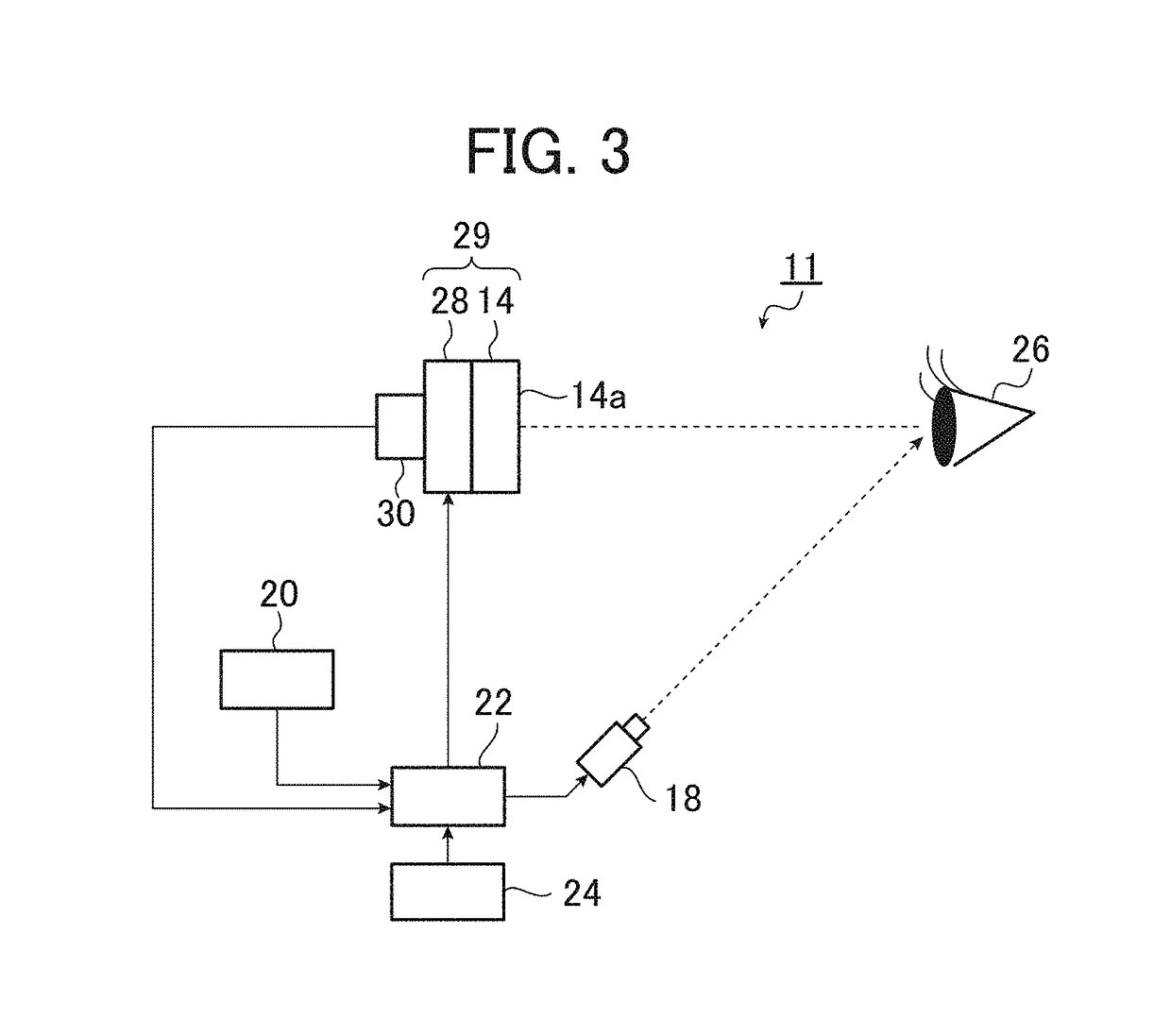
[0162]For the transmissive display apparatus 11 in the second embodiment of the invention, the change in contrast was obtained based on specific external factors in a specific environment.

[0163]In the second embodiment of the invention, visual sensitivity (contrast sensitivity (CS)) S(u) also changes depending on the light emission brightness (display brightness) of the display device, ambient light and the observation distance.

[0164]The visual sensitivity S(u) is defined by Formula (1) above.

[0165]In Formula (1), with an observation distance of 500 mm and an observation angle (X0) defined as a solid angle of 60 mm×60 mm, when the display brightness L ranges from 0.1 to 1000 cd / m2, the visual sensitivity (CS) S(u) can be presented as shown in FIG. 11.

[0166]FIG. 11 is a graph for explaining the change in visual sensitivity due to the display brightness, which is used in the present invention.

[0167]As can be seen from FIG. 11, for every display brightness ranging from 0.1 to 1000 cd / m...


PUM


Abstract

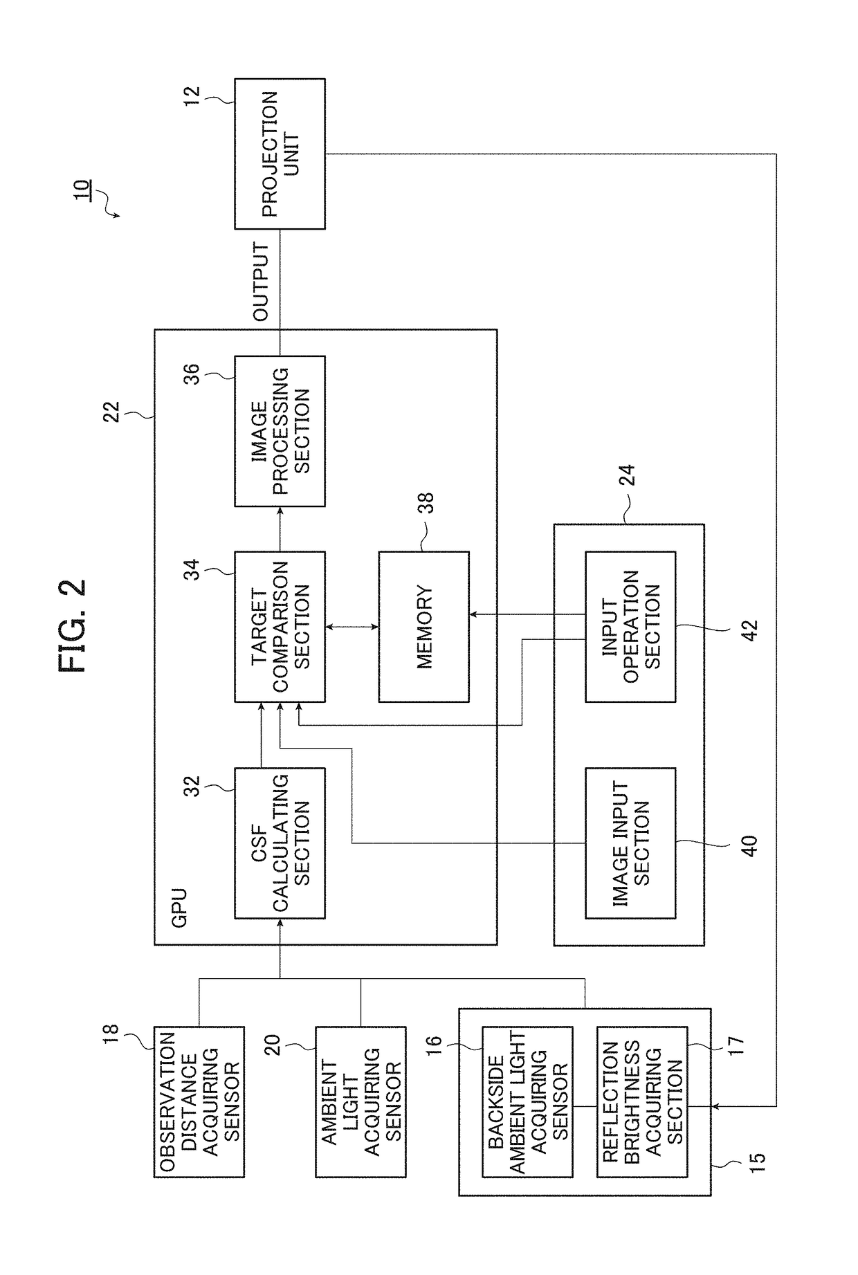
A display apparatus comprises a display device including an imagewise light emitting unit that emits imagewise light for displaying an input image, and a display surface member that includes a display surface that displays the input image as a displayed image, and transmits backside ambient light or reflects ambient light; an observation distance detecting section that detects an observation distance between the display surface and an observer; a display brightness acquiring section that acquires display brightness of the display device; an ambient light detecting section that detects the ambient light; and an image processing unit that performs image processing to adjust input spatial frequency characteristics of the input image based on the display brightness, the observation distance, and the ambient light such that display spatial frequency characteristics of the displayed image agree with target spatial frequency characteristics.

Description

CROSS-REFERENCE TO RELATED APPLICATIONS[0001]The present application claims priority under 35 U.S.C. § 119 to Japanese Patent Application No. 2015-240408, filed on Dec. 9, 2015. The above application is hereby expressly incorporated by reference, in its entirety, into the present application.BACKGROUND OF THE INVENTION[0002]The present invention relates to display apparatuses, particularly to display apparatuses such as a transmissive display apparatus capable of displaying images with the optimal contrast condition by optimizing an optical system of an observation environment (i.e., ambient light, observation distance, and display brightness (or brightness of background ambient light and a reflected image), or brightness of a translucent image), thereby improving the visibility.[0003]In recent years, transmissive display apparatuses have been proposed such as a mirror having an image display function or a mirror with a built-in monitor for displaying images taken by a camera and vi...

Claims


Application Information

Patent Timeline
Patent Type & Authority Patents(United States)
IPC IPC(8): G06T5/00G09G3/34G09G3/20G02B27/01G02B27/00
CPCG02B27/0101G02B27/0093G02B27/017G06T5/009G09G3/20G09G3/3406G09G2380/10G06T2207/20208G09G2320/066G09G2320/0626G09G2354/00G09G2360/144G09G2360/145G02B2027/0118
Inventor IWAMI, KAZUCHIKA
Owner FUJIFILM CORP
Why Eureka
Try Eureka