
Seismic sensor

a technology for seismic surveying and apparatus, applied in the direction of speed/acceleration/shock measurement, acceleration measurement using interia forces, instruments, etc., can solve the problems of requiring space and power for additional electronic circuitry, and partially defeating the mems advantages of size and weigh

Active Publication Date: 2018-11-27
BP EXPLORATION OPERATING CO LTD
View PDF17 Cites 4 Cited by
  • Summary
  • Abstract
  • Description
  • Claims
  • Application Information

AI Technical Summary

Benefits of technology

[0014]By providing an apparatus for use in seismic surveying where the proof mass comprises a power supply, so arranged to maximize sensitivity, linearity and robustness, the apparatus is able to save both size and weight in comparison to known devices where the sensor and power supply are separate entities. This in turn makes seismic surveying more efficient.
[0018]Known devices used for seismic surveying typically use complex sensors such as a moving coil within a magnetic field. The inventor has recognized that simpler lighter and more cost efficient apparatus can be constructed using piezoelectric elements. While piezoelectric pressure transducers are widely used in offshore marine surveys, the use of piezoelectric elements for onshore sensors is deemed inappropriate in the art as the accuracy of piezoelectric elements is deemed to be insufficient. However, the cost, size and weight gains afforded by having the proof mass comprising the power supply enable an increased number of such apparatuses to be deployed. The larger number of apparatuses, in comparison to historical and current practice, enable the accuracy of the system as a whole to be maintained and enhanced, despite any reduction of the accuracy of a single apparatus.
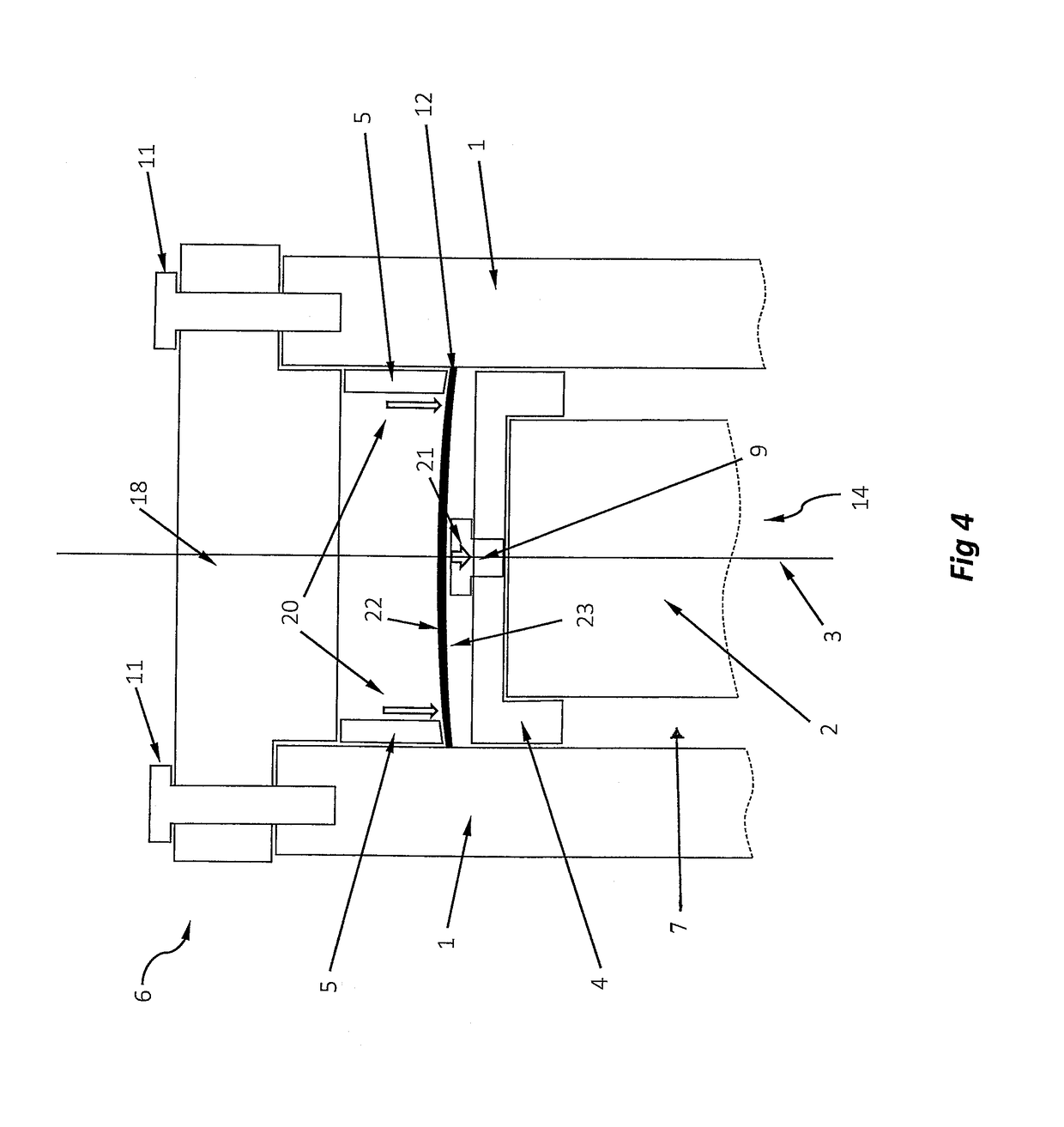
[0037]In embodiments, the apparatus may be constructed such that a flattened member is forced towards the elongated member via a clamping force on the perimeter thereof. This may cause the flattened member to flex, causing the concavity of the surface of the flattened member. This serves to effectively hold the elongated member in place, while enabling movement of the elongated member.
[0041]The apparatus of any one of the preceding claims, wherein the body is provided with a protrusion to engage the proof mass so as to limit movement of the proof mass, for example to limit movement of the proof mass in the first direction. This can prevent the proof mass pushing the piezoelectric element so far that it damages the piezoelectric element, for example in the event the apparatus is dropped.

Problems solved by technology

This required additional electronic circuitry requires space and power and partially defeats the MEMS advantages of size and weight compared to the passive moving coil geophone.

Method used


Image

  • Seismic sensor
  • Seismic sensor
  • Seismic sensor

Examples


Embodiment Construction

[0051]Several parts and components of the invention appear in more than one Figure; for the sake of clarity the same reference numeral will be used to refer to the same part and

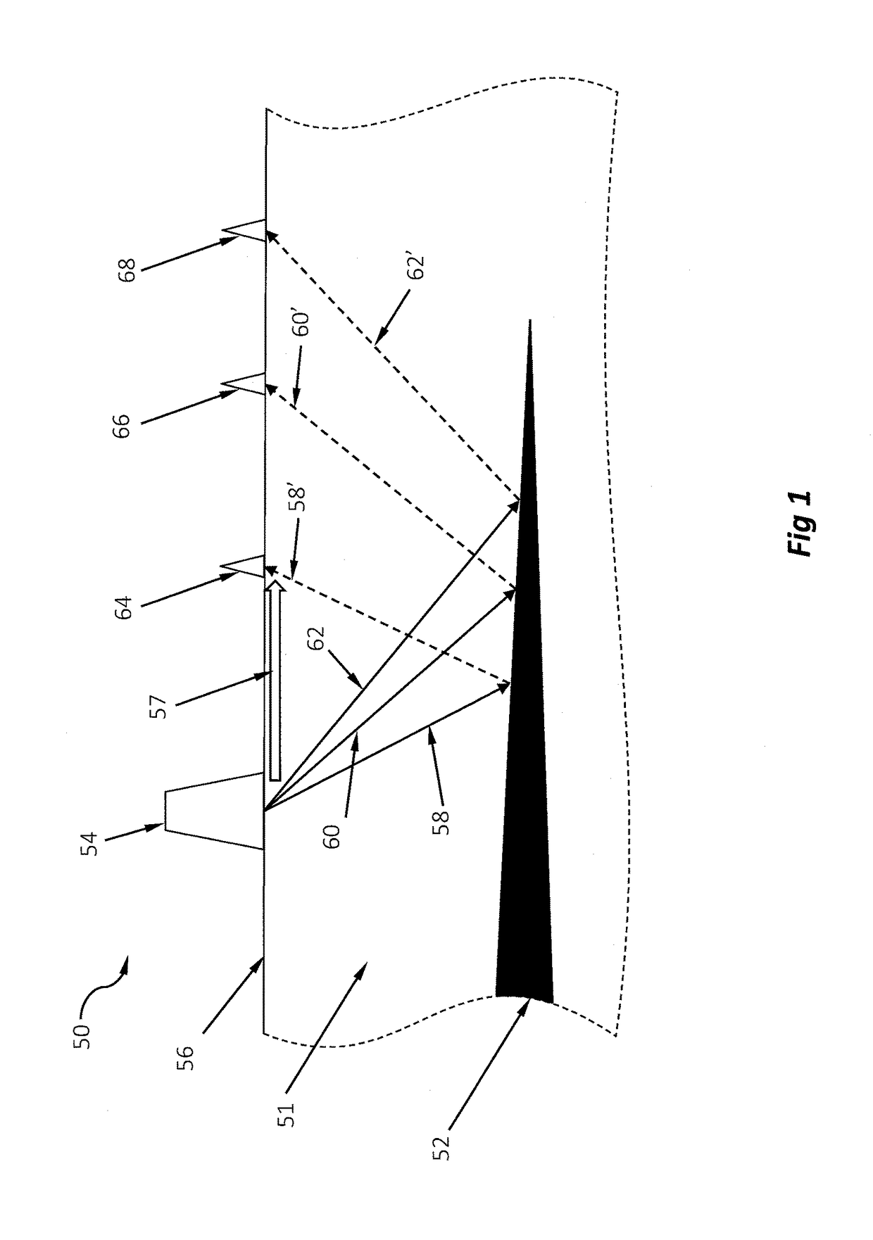
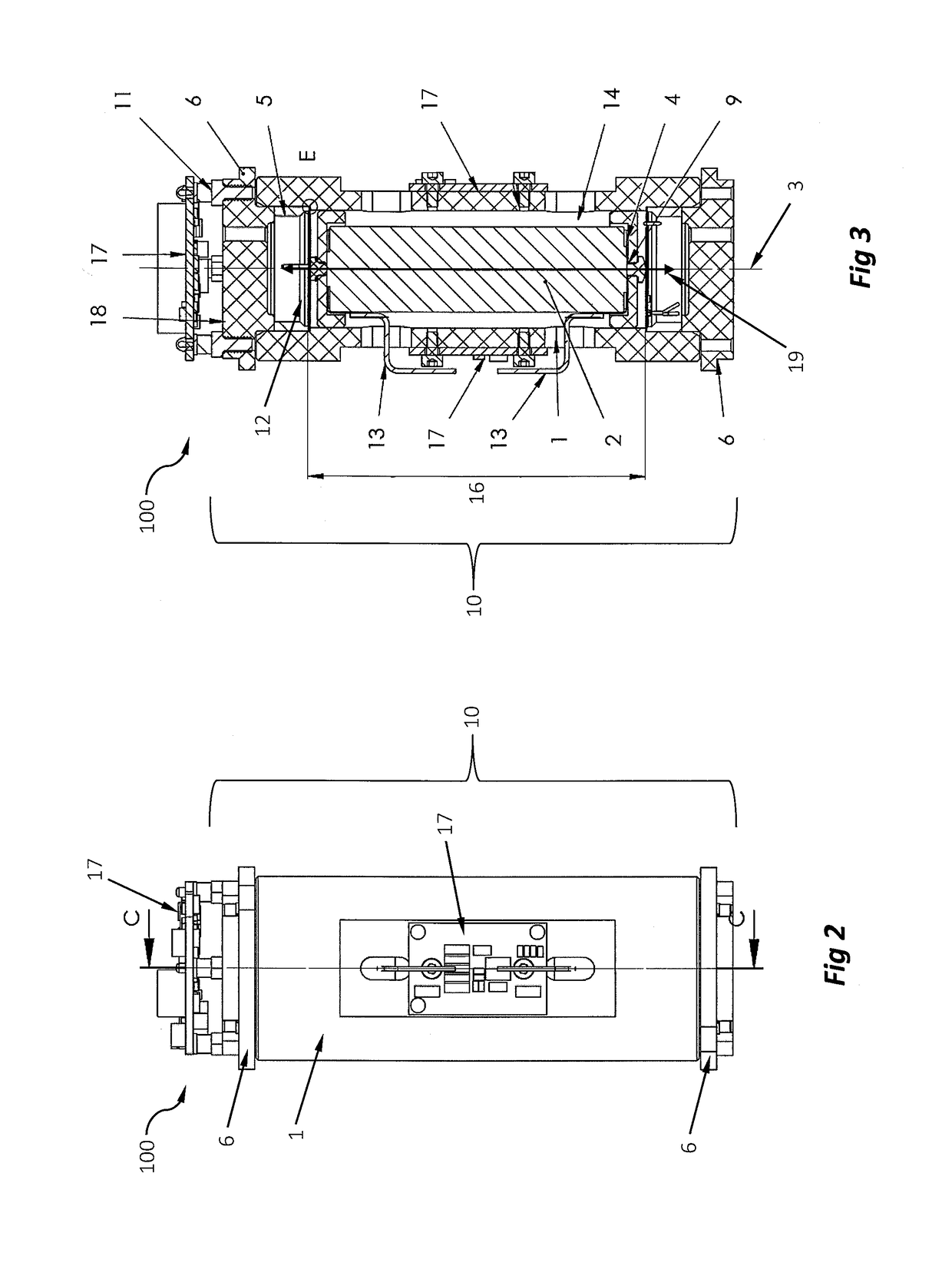
[0052]A brief description of seismic sensing will first be described with reference to FIG. 1, followed by a description of a seismic sensor with reference to FIGS. 2, 3 and 4.

[0053]FIG. 1 shows a simplified representation of a seismic surveying system 50 surveying the subsurface of the earth 51. The subsurface 51 will, for the purposes of this illustration be assumed to have a relatively uniform composition, except for layer 52. This layer may, for example, be a different type of rock to the rest of the subsurface 51, and therefore be differing in e.g. density and / or elastic velocity to the rest of the subsurface 51.

[0054]A seismic source 54 is located on the surface 56 of the earth. The seismic source 54 creates controlled seismic waves for propagation through the subsurface 51. Known examples of seismic so...


PUM


Abstract

A seismic survey apparatus includes a body, a proof mass, at least one sensor arranged to detect movement of the proof mass relative to the body. In addition, the seismic survey apparatus includes electronic circuitry connected to the at least one sensor. The electronic circuitry is configured to receive and process an output of the sensor. A power supply is arranged to provide electrical power to the electronic circuitry with the power supply being an integral part of the proof mass.

Description

CROSS-REFERENCE TO RELATED APPLICATIONS[0001]This application is a 35 U.S.C. § 371 national stage application of PCT / EP2015 / 055240 filed Mar. 12, 2015 and entitled “Seismic Sensor,” which claims priority to U.S. Provisional Application No. 61 / 953,086 filed Mar. 14, 2014 and entitled “Seismic Sensor,” both of which are hereby incorporated herein by reference in their entirety for all purposes.STATEMENT REGARDING FEDERALLY SPONSORED RESEARCH OR DEVELOPMENT[0002]Not applicable.BACKGROUND[0003]The present invention relates to an apparatus for use in seismic surveying.[0004]Seismic surveying, or reflection seismology, is used to map the Earth's subsurface. A controlled seismic source provides a low frequency seismic wave which travels through the subsurface of the Earth. At interfaces between dissimilar rock layers, the seismic wave is partially reflected. The reflected waves return to the surface where they are detected by one or more of seismic sensors. Ground vibration detected at the...

Claims


Application Information

Patent Timeline
Patent Type & Authority Patents(United States)
IPC IPC(8): G01V1/16G01V1/18G01P15/09G01H11/08
CPCG01V1/164G01H11/08G01P15/09G01V1/181G01P15/0922G01V2210/1427G01V2210/1423G01V2210/1425
Inventor BOUSKA, JOHN GERARD
Owner BP EXPLORATION OPERATING CO LTD
Learn More