
Extremity imaging for animals

a technology of extreme imaging and animals, applied in the field of standing subjects radiographic imaging, can solve the problems of cbct damage, detector or source position liable to receive a kick, and equines are finicky animals and tend to react erratically

Inactive Publication Date: 2018-11-27
CARESTREAM HEALTH INC
View PDF16 Cites 9 Cited by
  • Summary
  • Abstract
  • Description
  • Claims
  • Application Information

AI Technical Summary

Benefits of technology

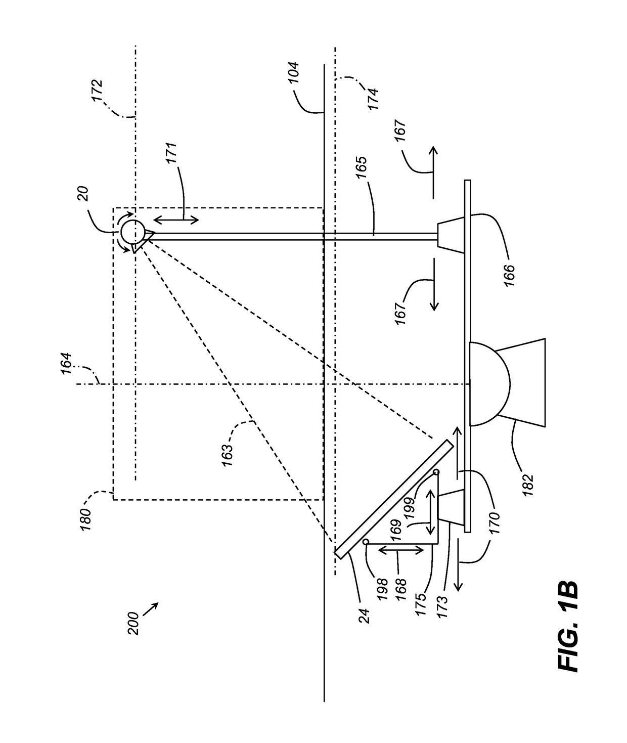
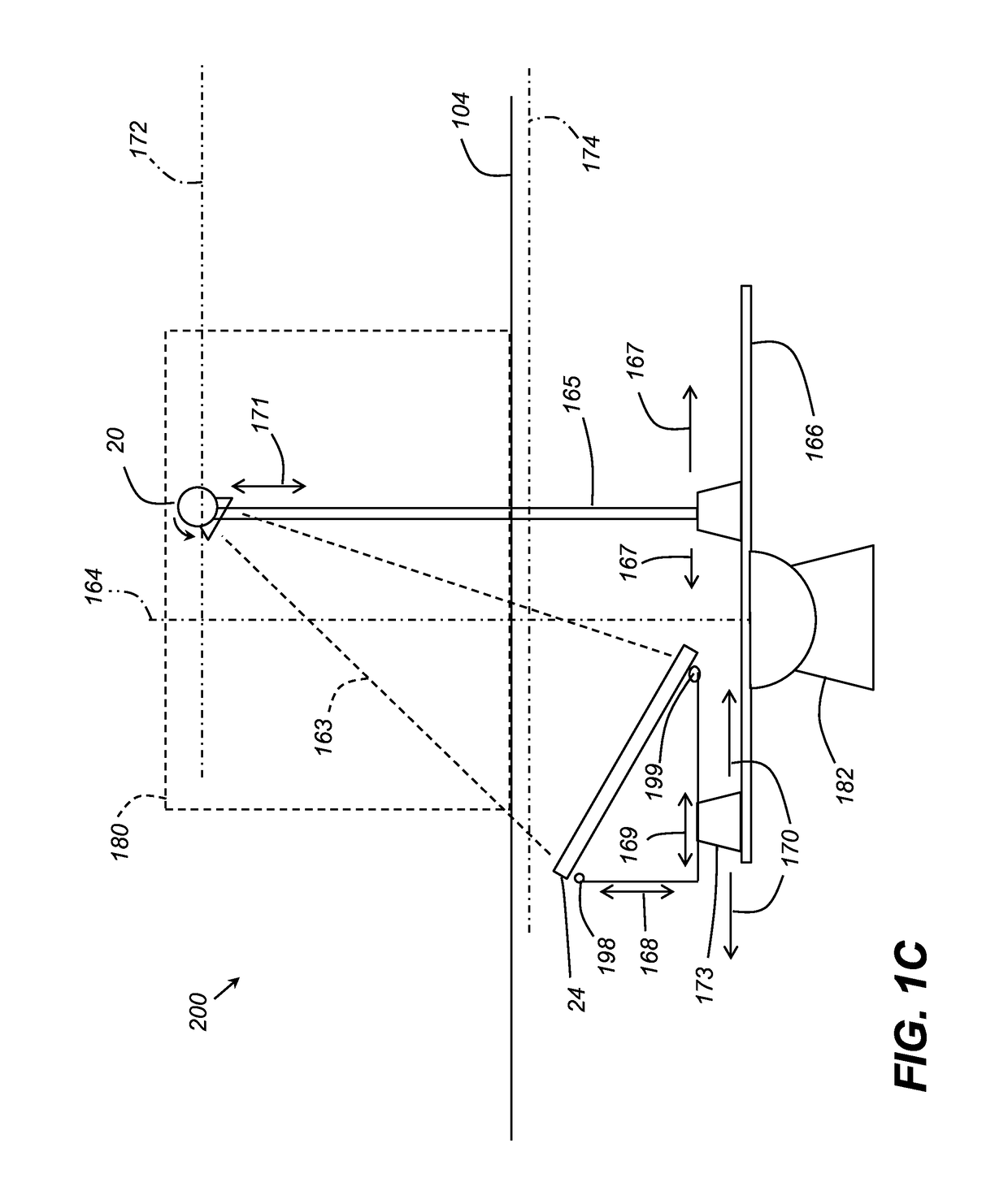
[0009]The detector may be placed in a track under the animal in such a manner that there is absolutely no possibility for the animal to physically interact with the detector. This greatly reduces the chance of equipment damage, and if damage occurs the source will likely be the damaged part. This is significant as the detector is the more expensive component. The configuration of the CBCT system, or CBCT stall will be described herein.
[0011]The detector may be placed in a race below the floor of the imaging system so that the animal never has an opportunity to physically access the detector. Consequently, the animal can be brought into the CBCT-stall and allowed to walk over the detector until it is suitably positioned. This also has the advantage in that the animal does not perceive any movement of the device, which could cause the animal to bolt or become startled.
[0014]The initial placement of the detector and source need to be sensed and reported in order to perform any subsequent reconstruction algorithm. This can be accomplished with multiple methods. The information needed includes the starting rotation angles, the height of the source, the declination angle of the source, the radial position of the detector, the tilt angle of the detector, the number of projection images captured and the angle between successive projections. An overall control system to coordinate the imaging system is standard in any CBCT system. The reconstruction of the 3D volume from the projection images can be performed using a standard algebraic reconstruction method. However, modifying the algorithm to account for specific aspects of a customized configuration is possible.
[0015]In one embodiment, the system eliminates a major component of the system from restricting the movement of the animal either in positioning the animal or in case the animal moves unexpectedly. This reduces the chance of injury to the animal and damage to the equipment. Although several examples disclosed herein depict an exemplary subject animal as a horse, the disclosed embodiments may be used for a variety of animals. For example, bovine imaging may be useful at a dairy farm to monitor health of cows' hooves. Other large and smaller animals may be safely radiographically imaged such as at a zoo, for example.
[0017]The apparatus includes a moveable x-ray source that is attached to the system, though above the detector assembly. The source has the ability to make exposures at a rate and dose adequate for CBCT applications; for instance at 20 exposures per second. The source is also synchronized with the detector so both subsystems move in parallel orbital planes about the axis-of-rotation and with the positions within their respective orbits being approximately 180 degrees apart. The x-ray source also can be positioned in order that its location is not in the immediate physical proximity to the animal, or is not visible to the animal. This also reduces the potential for damage or injury in case the animal attempts to flee. An advantage that may be realized in the practice of some disclosed embodiments of the imaging system is convenient and portable radiographic imaging of animals at remote sites.

Problems solved by technology

However, equines are finicky animals and tend to react erratically in situations that they are uncomfortable.
Two problems arise from such a configuration.
The first is that either the detector or the source is in the position liable to receive a kick, and subsequent damage to the CBCT, from the animal if it is startled.
Second if the animal decides to flee, then the components would be in likely path of the animal resulting in possible damage to the equipment or injury to the animal.
This greatly reduces the chance of equipment damage, and if damage occurs the source will likely be the damaged part.
This is significant as the detector is the more expensive component.

Method used


Image

  • Extremity imaging for animals
  • Extremity imaging for animals
  • Extremity imaging for animals

Examples


Embodiment Construction

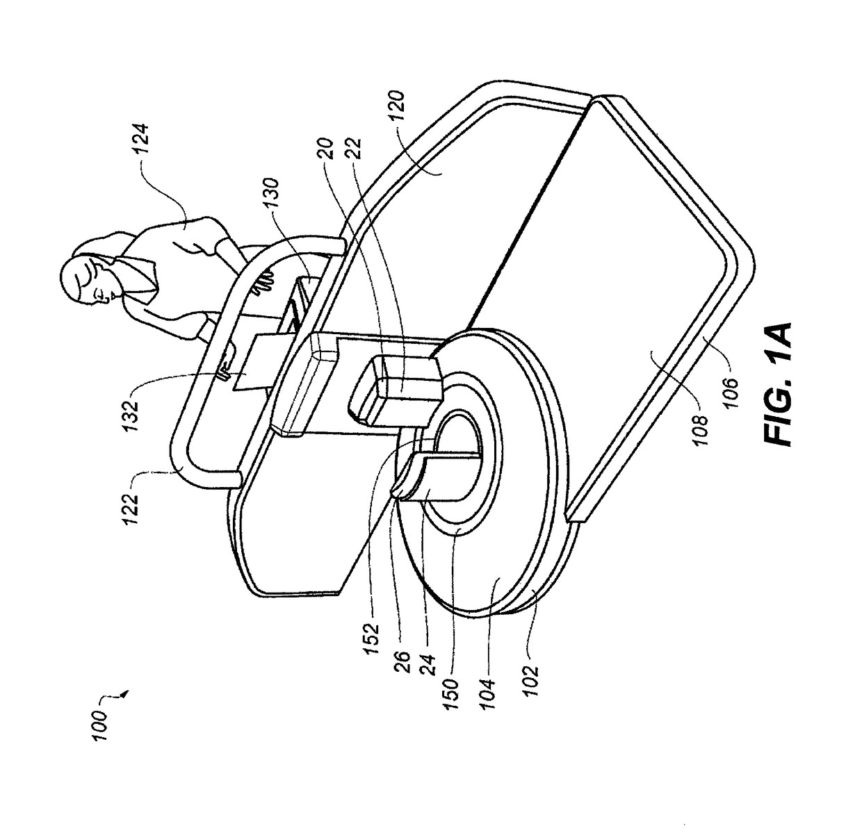
[0038]It may be helpful to briefly explain a prior art embodiment of an animal imaging system before describing the novel embodiment of the present invention that is illustrated beginning with FIG. 1B. With reference to the prior art embodiment of FIG. 1A, there is illustrated an embodiment of an exemplary radiographic extremity imaging system 100. The extremity imaging system 100 may include a substantially circular support base 102 having a generally planar top surface 104 to provide a platform for supporting a subject animal, such as its forelegs, hind legs, or both. The support base 102 may be configured to be rotatable about a central axis through the center of the support base 102, as described herein. Attached to the support base 102 may be a platform 106 having a generally planar top surface 108 to support an animal to be imaged, such as its forelegs or hind legs. The platform 106 may be movable about the perimeter of the support base 102 to assist in positioning a subject a...


PUM


Abstract

An apparatus captures radiographic images of an animal standing proximate the apparatus. A moveable x-ray source and a digital radiographic detector are hidden from view of the animal and are revolved about a portion of the animal's body to capture one or a sequence of radiographic images of the animal's body.

Description

CROSS REFERENCE TO RELATED APPLICATIONS[0001]This application claims priority to U.S. Patent Application Ser. No. 62 / 174,010, filed Jun. 11, 2015, in the name of Ray et al., and entitled EXTREMITY IMAGING FOR ANIMALS.BACKGROUND OF THE INVENTION[0002]The subject matter disclosed herein relates to radiographic imaging of standing subjects, in particular, to applications using Cone-Beam Computed Tomography imaging.[0003]Cone-Beam Computed Tomography (CBCT) imaging would provide a useful tool for diagnosis and treatment assessment, planning, and tracking for an animal as the imaging subject. Certain exemplary CBCT imaging apparatus and methods described herein may address a number of practical challenges for performing CBCT imaging in veterinary applications that relate to considerations such as protection and cleaning of the equipment, shielding of technicians and practitioners during imaging, humane treatment of the animal subject in positioning and restraining the subject for imaging...

Claims


Application Information

Patent Timeline
Patent Type & Authority Patents(United States)
IPC IPC(8): A61B6/03A61D3/00H05G1/04A61B6/00A01K29/00A61B6/04A61B6/02A61B6/10
CPCA61B6/035A61B6/508A61B6/4435A61B6/589A61B6/4233A61B6/5205A61D2003/006H05G1/04A01K29/005A61B6/027A61B6/032A61B6/04A61B6/102A61B6/4007A61B6/4085
Inventor RAY, LAWRENCE A.GINDELE, EDWARD B.
Owner CARESTREAM HEALTH INC
Learn More