
Rolling bearing

a rolling bearing and bearing technology, applied in the direction of bearings, shafts and bearings, rotary machine parts, etc., can solve the problems of adverse influence on the part to which the toner is attached, image quality deterioration, etc., to achieve small torque, reduce agitation and shearing of grease, and improve lubricating characteristics

Inactive Publication Date: 2018-11-20
NTN CORP
View PDF26 Cites 0 Cited by
  • Summary
  • Abstract
  • Description
  • Claims
  • Application Information

AI Technical Summary

Benefits of technology

The present invention provides a rolling bearing with improved lubrication characteristics. The bearing includes a flocking part made of synthetic resin fiber which is formed on a surface of a member and contains a lubricant such as grease or lubricating oil. This flocking part is fixed to the member and retains the lubricant without collapsing the shape of the pocket part or deteriorating the bearing function. The bearing also includes a conductive passage which ensures electrical conductivity between the inner and outer rings through the flocking part or the retainer. This reduces the torque and increases the life of the bearing. The flocked fiber is chemically stable, uniform, and dense and the conduction is secured for a long time.

Problems solved by technology

It has been known that if the bearing is charged, the photosensitive part to which the toner is attached is adversely influenced and the image quality will be deteriorated.

Method used


Image

  • Rolling bearing
  • Rolling bearing
  • Rolling bearing

Examples


example 1

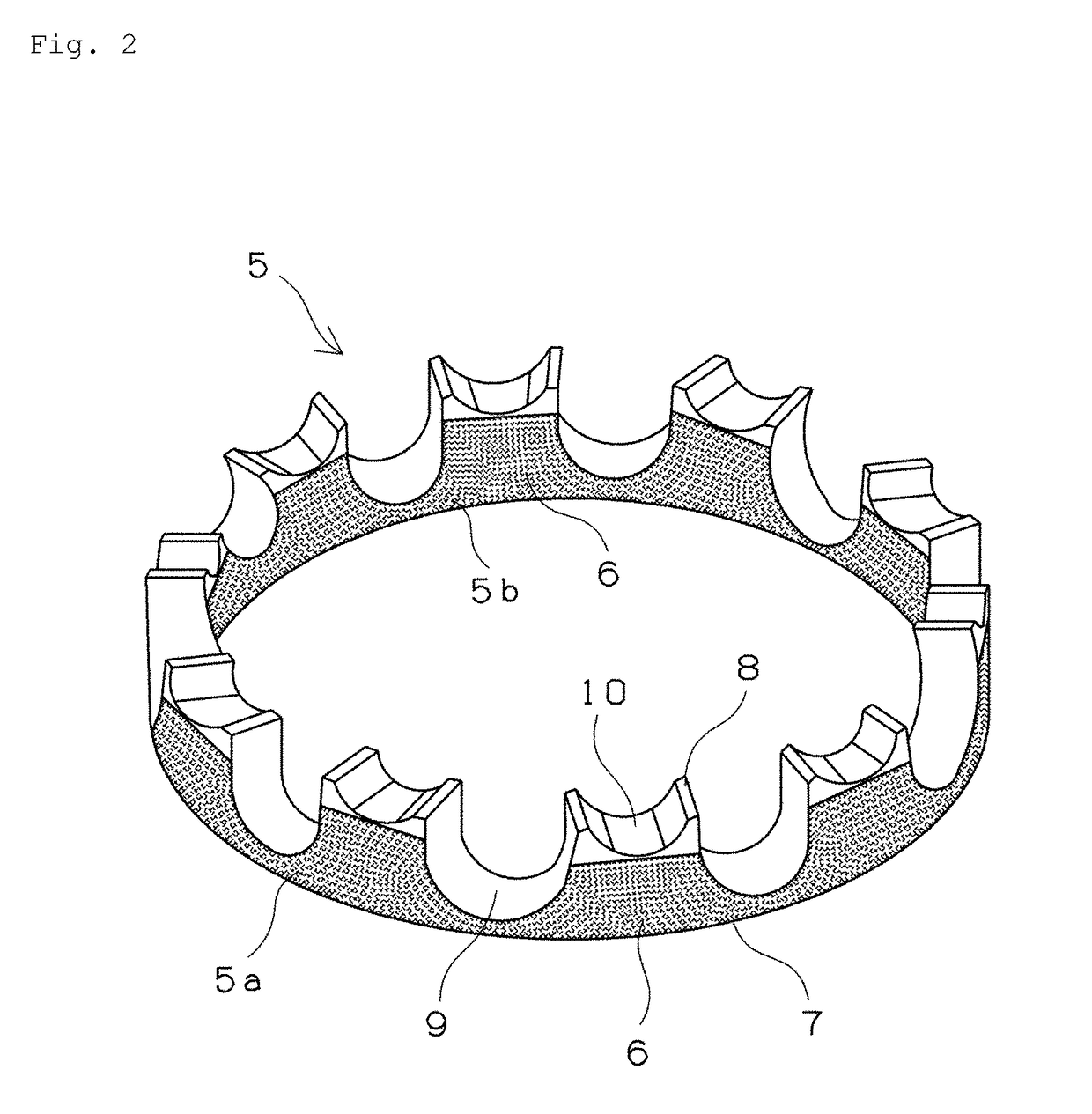
[0082]A resin crown retainer with the shape illustrated in FIG. 2, which can be used for the 6206 rolling bearing (deep groove ball bearing), was manufactured through injection molding. The resin material is nylon 66 (containing 30 vol % of glass fiber). An adhesive was applied to the inner and outer diameter surfaces of the retainer (areas illustrated in FIG. 2) and the flocking part including polyamide resin fiber was formed through the electrostatic flocking. This flocking retainer was incorporated in the 6206 rolling bearing (deep groove ball bearing), and the grease (lithium soap+ester oil) was enclosed in the in-bearing space by 70 vol % in static space volume ratio. Then, the space was sealed with the shield plate and the sample bearing was thus obtained. The obtained sample bearing was subjected to the torque measurement test 1 below, so that the change in rotational torque over time was examined.

[0083]The sample bearing was fixed in a vertical chamber under the condition th...

example 2

[0088]A resin crown retainer with the shape illustrated in FIG. 2 was manufactured through injection molding. The resin material is nylon 66 (containing 30 vol % of glass fiber). An adhesive was applied to the entire surface of the retainer (except the pocket part) and the flocking part including polyamide resin fiber was formed through the electrostatic flocking. This flocking retainer was incorporated in the rolling bearing (bearing size: 20 mm in inner diameter, 47 mm in outer diameter, and 14 mm in width), and the urea grease was enclosed in the in-bearing space by 95 vol % in static space volume ratio (35 vol % in the entire space ratio). The sample bearing was thus obtained. The obtained sample bearing was subjected to the torque measurement test 2 and the high-temperature durability test below.

[0089]The sample bearing was fixed in a vertical chamber under the condition that the atmosphere was the room temperature (25° C.) and the number of rotation was set to 3600 rpm, and wa...


PUM


Abstract

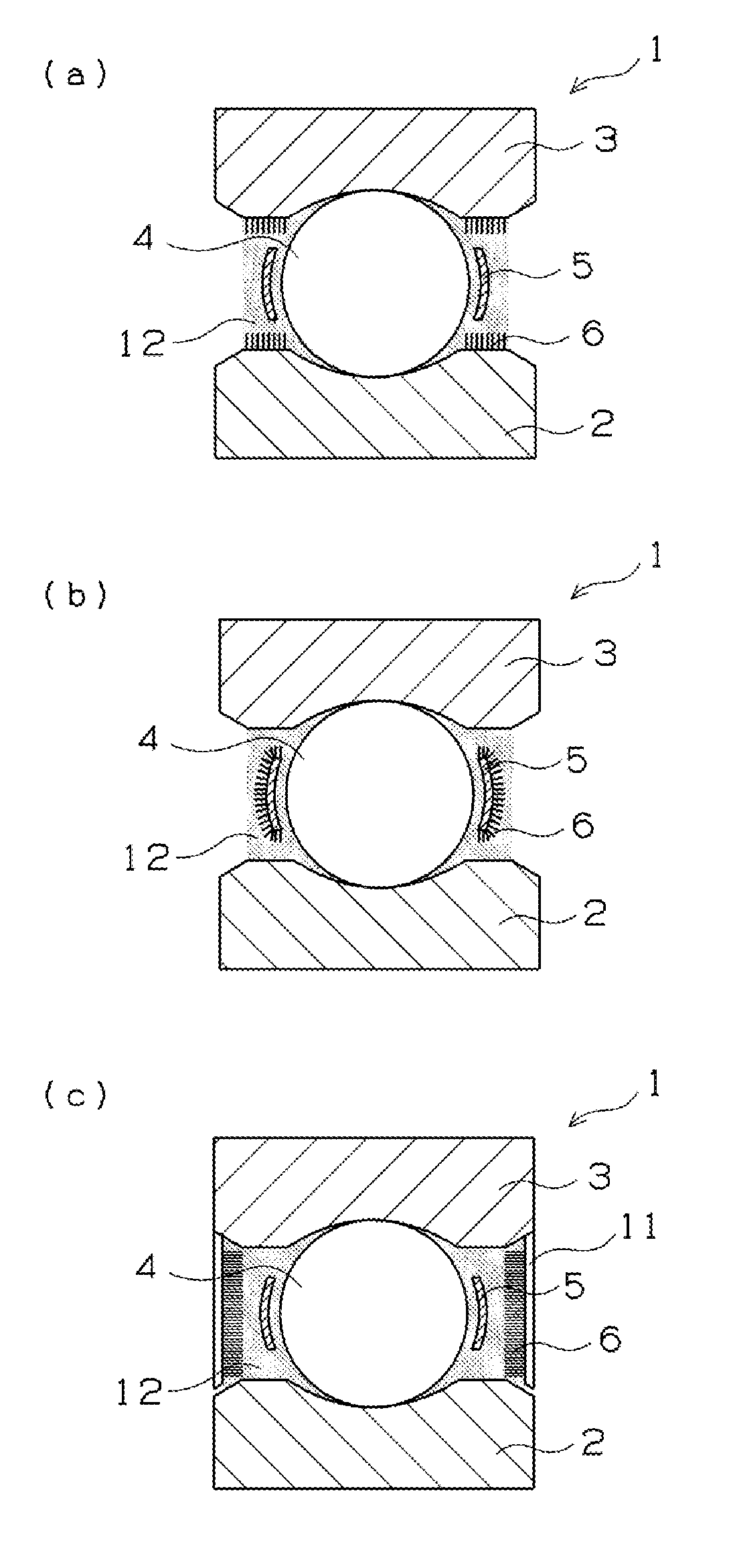
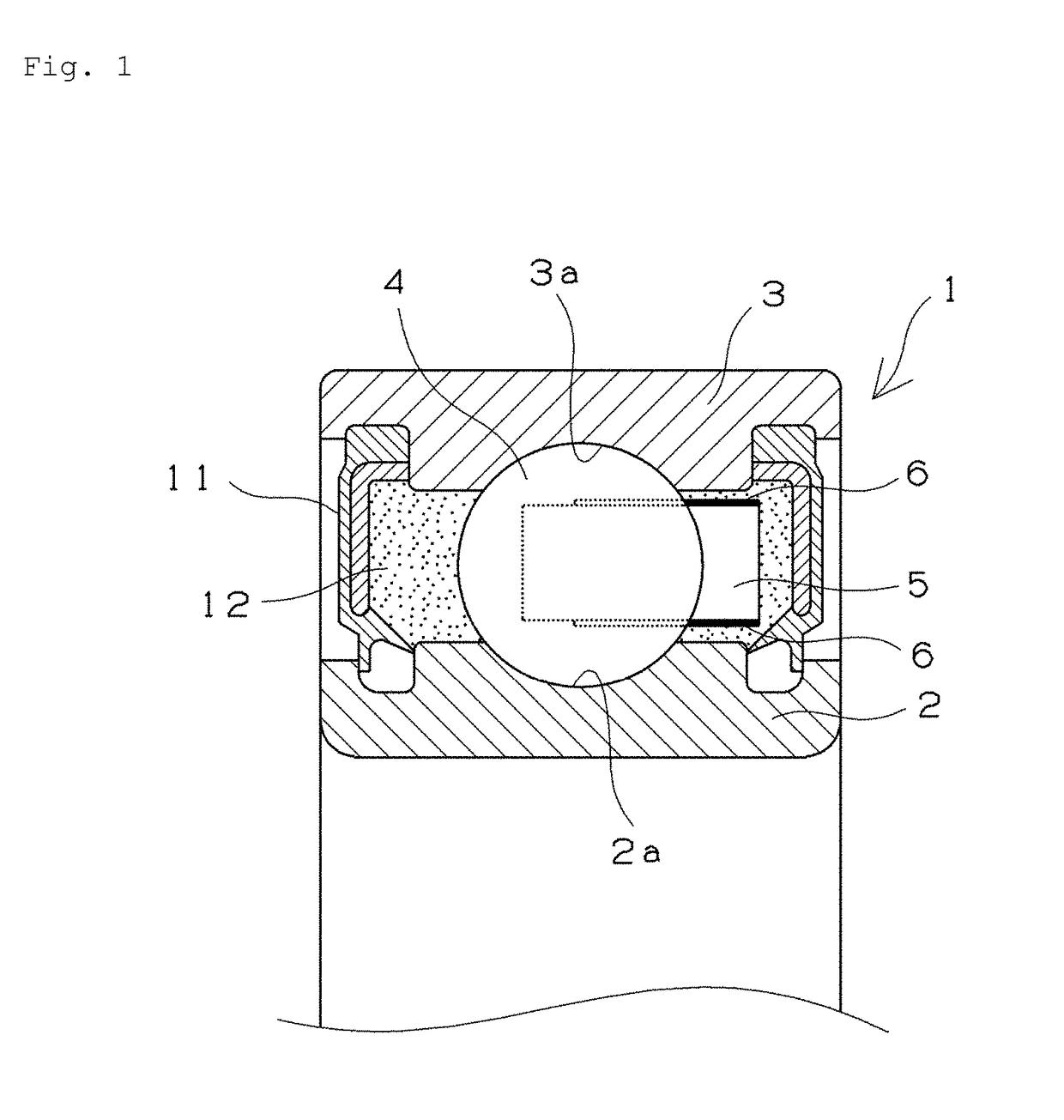
A rolling bearing that can easily achieve the higher lubricating characteristic including the smaller rotational torque while employing the existing bearing shape and lubricant is provided. A rolling bearing 1 includes: an inner ring 2 and an outer ring 3 as a race ring; a plurality of rolling elements 4 held between the inner and outer rings; a retainer 5 that retains the rolling elements 4; a sealing member 11 provided at openings on opposite ends in an axial direction of the inner ring 2 and the outer ring 3; and grease 12 to be enclosed in an in-bearing space. At least one member selected from the inner ring 2, the outer ring 3, the retainer 5, and the sealing member 11 is provided with a flocking part 6 formed by flocking fiber on a surface of the member which is in contact with the grease 12.

Description

TECHNICAL FIELD[0001]The present invention relates to a rolling bearing which is lubricated with lubricating oil or grease.BACKGROUND ART[0002]A rolling bearing generally includes an inner ring, an outer ring, a rolling element, and a retainer. An open end thereof may be provided with a sealing member in order to prevent the intrusion of foreign substances from the outside or the leakage of the lubricant enclosed inside. The lubrication inside the bearing is carried out by the lubricant such as oil or grease, and various devises have been made in order to improve the lubricating characteristic of the bearing.[0003]For example, Patent Document 1 has suggested the technique of improving the lubricating characteristic by forming a lubricating film on a retainer. Patent Document 1 describes a rolling device whose outer member, inner member, rolling element, and the like have their surface provided with a predetermined lubricating film. The lubricating film is formed of a solid lubricant...

Claims


Application Information

Patent Timeline
Patent Type & Authority Patents(United States)
IPC IPC(8): F16C41/00F16C33/78F16C19/06F16C33/66F16C33/44F16C33/41
CPCF16C41/002F16C19/06F16C33/445F16C33/6633F16C33/7853F16C33/7816H05K999/99F16C33/416F16C33/6637F16C2202/32
Inventor KAWAMURA, MITSUOOBATA, TOMOHIKO
Owner NTN CORP
Learn More