
System and apparatus for clothing with embedded passive repeaters for wireless communication

a passive repeater and wireless communication technology, applied in the field of wireless communication technology, can solve the problems of deteriorating radio frequency (rf) signals, multipath interference, weak signal strength areas still exist, etc., and achieve the effect of enhancing wireless connectivity

Active Publication Date: 2018-11-13
HAPPY SOAP LLC
View PDF3 Cites 1 Cited by
  • Summary
  • Abstract
  • Description
  • Claims
  • Application Information

AI Technical Summary

Benefits of technology

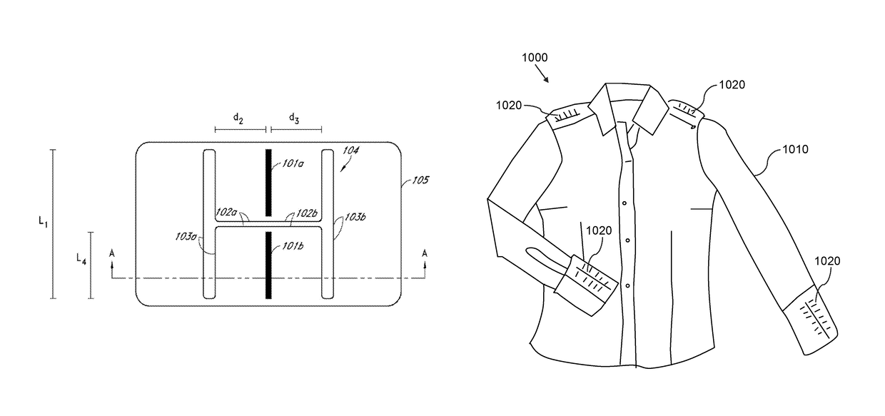
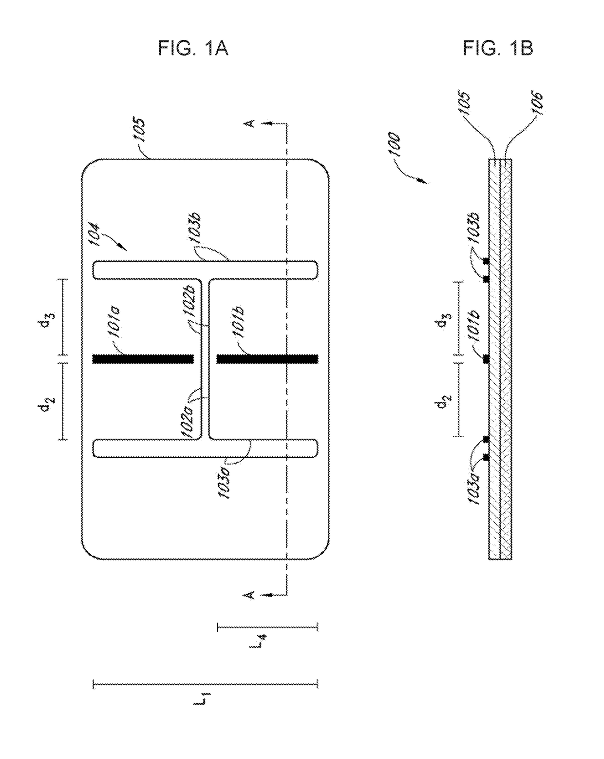
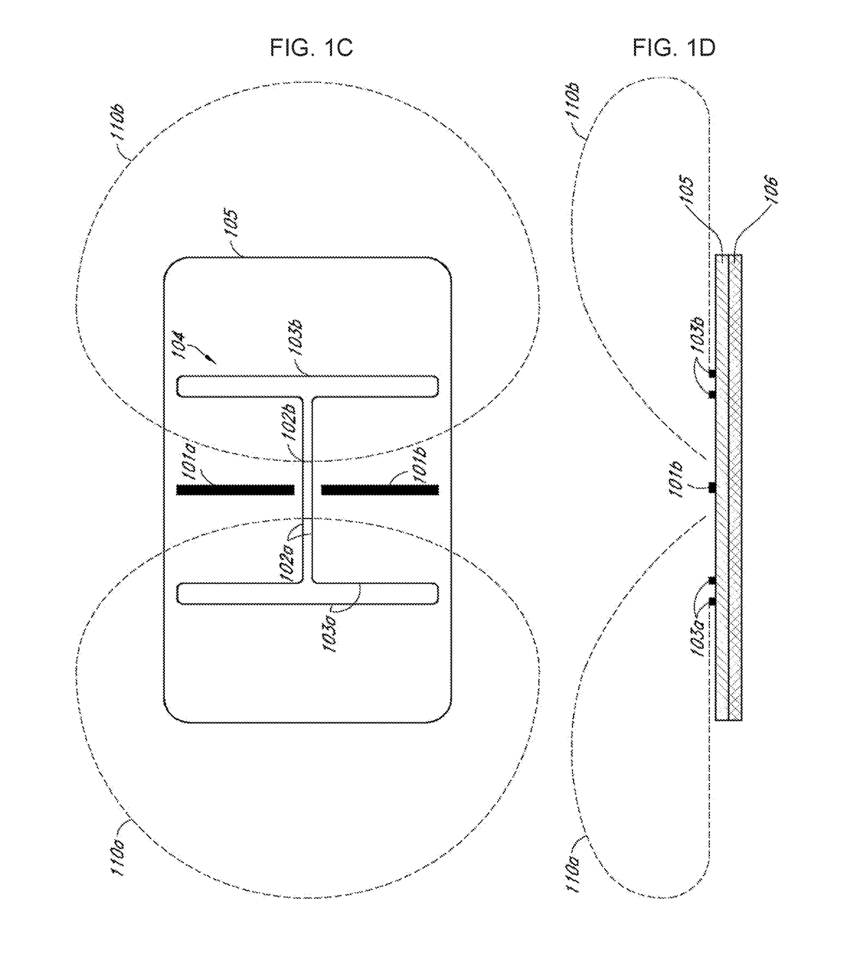
The present invention provides improvements to devices and systems for enhancing wireless connectivity. Specifically, the invention includes a passive repeater garment with a plurality of antennas mounted on a clothing item, as well as a system of multiple personal assemblies of passive repeater garments. The antennas include folded dipole antennas with electromagnetically reflective layers and conductive connectors. The invention also includes a conductive connector and a dielectric separator to electrically isolate the reflector from the conductive connector. The technical effects of the invention include improved wireless connectivity, improved signal quality, and improved coverage.

Problems solved by technology

However, despite the efforts of network operators and consumer equipment makers to provide seamless wireless communication coverage, areas of weak signal strength still exist, even in richly serviced areas such as urban centers.
For example, within a substantially enclosed environment, such as a vehicle or building, the materials of the vehicle or building can cause shadowing, shielding and / or multipath interference that deteriorate radio frequency (RF) signals.
In a dense urban area, the surrounding buildings create a multipath environment where signal reflections destructively combine in locations that are difficult to predict.
The destructive interference reduces receivable RF signals to the point where wireless communication can be virtually impossible at the frequency and power levels used in the wireless system.

Method used


Image

  • System and apparatus for clothing with embedded passive repeaters for wireless communication
  • System and apparatus for clothing with embedded passive repeaters for wireless communication
  • System and apparatus for clothing with embedded passive repeaters for wireless communication

Examples


Embodiment Construction

[0043]Before describing the invention in detail, it should be observed that the present invention resides primarily in a novel and non-obvious combination of elements and process steps. So as not to obscure the disclosure with details that will readily be apparent to those skilled in the art, certain conventional elements and steps have been presented with lesser detail, while the drawings and specification describe in greater detail other elements and steps pertinent to understanding the invention.

[0044]The following embodiments are not intended to define limits as to the structure or method of the invention, but only to provide exemplary constructions. The embodiments are permissive rather than mandatory and illustrative rather than exhaustive.

[0045]Some embodiments provide a relatively small antenna apparatus that acts as a passive repeater. The antenna apparatus can be designed to facilitate radio frequency (RF) signal gain for a collection or range of frequencies. Some embodime...


PUM


Abstract

A passive repeater garment includes a clothing item and a plurality of flexible antenna apparatuses, each including an electromagnetically reflective layer; an insulation layer, which can be dielectric; an arrangement of conductors, including a first antenna, a second antenna, a coupling element, a reflector; an antenna layer; and a protective cover layer. The conductors can be made from conductive threads. The first and second antennas can include a dipole antenna, a rhombic antenna, a planar antenna, or a Yagi-Uda antenna, and an undulating portion. Also disclosed is a system of passive repeater garments, including a plurality of personal assemblies of passive repeater garments, each assembly configured for a human user, and including a plurality of passive repeater garments.

Description

CROSS-REFERENCE TO RELATED APPLICATIONS[0001]This application claims the benefit of U.S. Provisional Application No. 62 / 125,841, filed Feb. 2, 2015. Additionally, this application is a continuation-in-part of U.S. Non-Provisional application Ser. No. 14 / 162,357, filed Jan. 23, 2014, which is a continuation of U.S. Non-Provisional application Ser. No. 13 / 856,250, filed Apr. 3, 2013, which is a continuation of U.S. Non-Provisional application Ser. No. 12 / 884,056, filed Sep. 16, 2010, which claims priority from U.S. Provisional Application No. 61 / 373,222, filed Aug. 12, 2010, and U.S. Provisional Application No. 61 / 243,120, filed Sep. 16, 2009.FIELD OF THE INVENTION[0002]The present invention relates generally to the field of wireless communications technology, and more particularly to methods, devices, and systems for flexible fabric antennas, which are embedded into clothing in order to function as passive repeaters for transmission of wireless signals.BACKGROUND OF THE INVENTION[000...

Claims


Application Information

Patent Timeline
Patent Type & Authority Patents(United States)
IPC IPC(8): H01Q1/27H01Q19/30H01Q9/16H01Q25/00
CPCH01Q19/30H01Q9/16H01Q1/273H01Q25/005
Inventor WALKER, MICHAEL CLYDE
Owner HAPPY SOAP LLC
Learn More