Gas turbine combustor with annular flow sleeves for dividing airflow upstream of premixing passages
a technology of combustor and annular flow sleeves, which is applied in the direction of burners, combustion types, combustion processes, etc., can solve the problems of increasing the number of parts, reducing the stability of combustion, and increasing the number of fuel systems, so as to reduce the amount of air differences, simplify the fuel supply system, and reduce the effect of air flow
- Summary
- Abstract
- Description
- Claims
- Application Information
AI Technical Summary
Benefits of technology
Problems solved by technology
Method used
Image
Examples
first embodiment
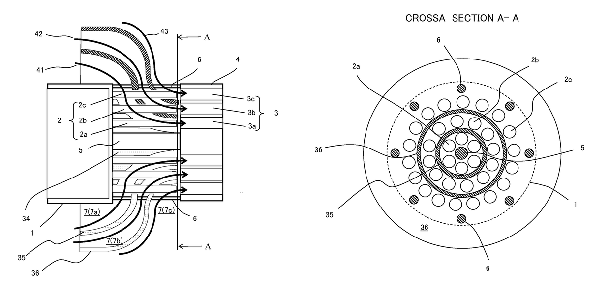
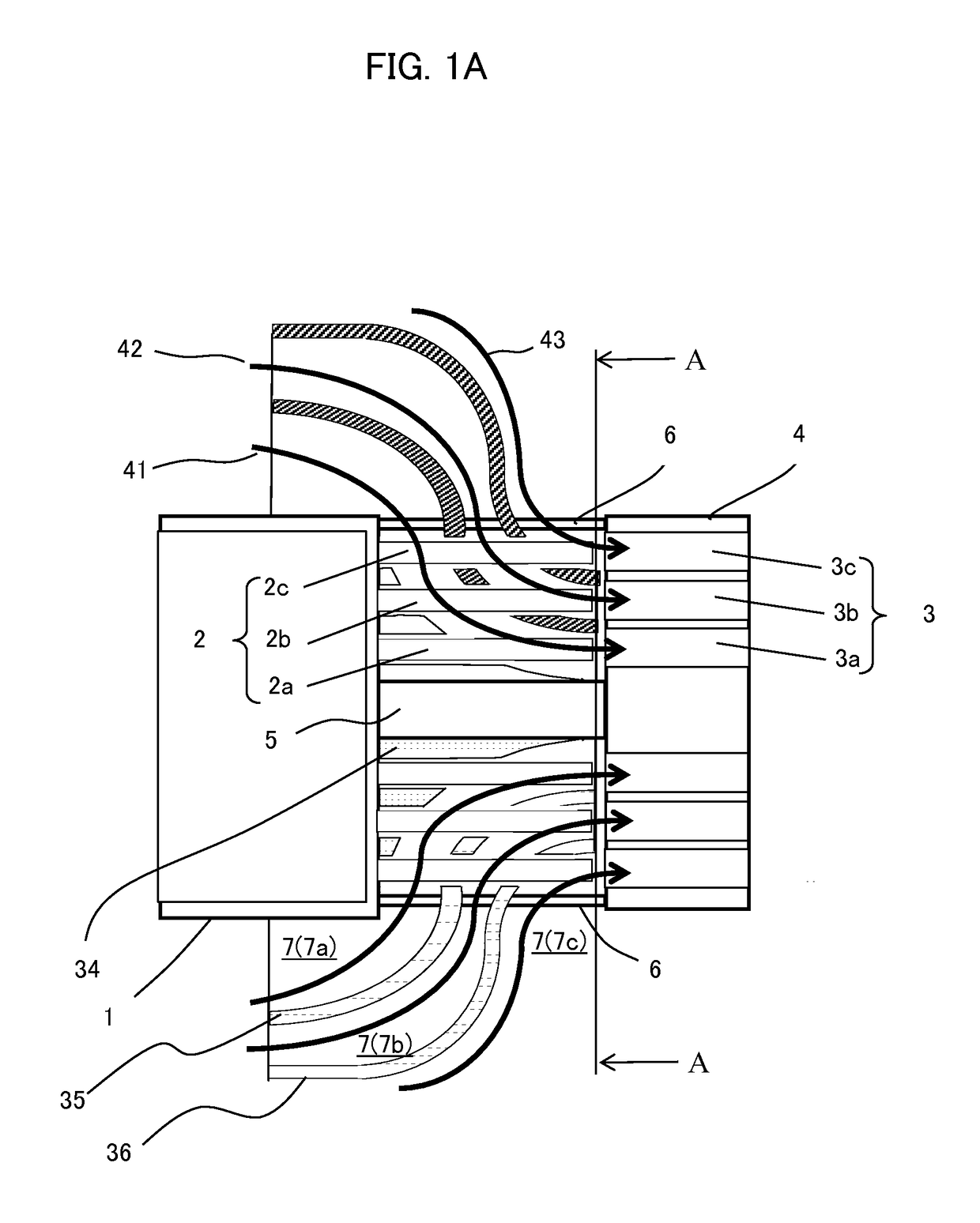
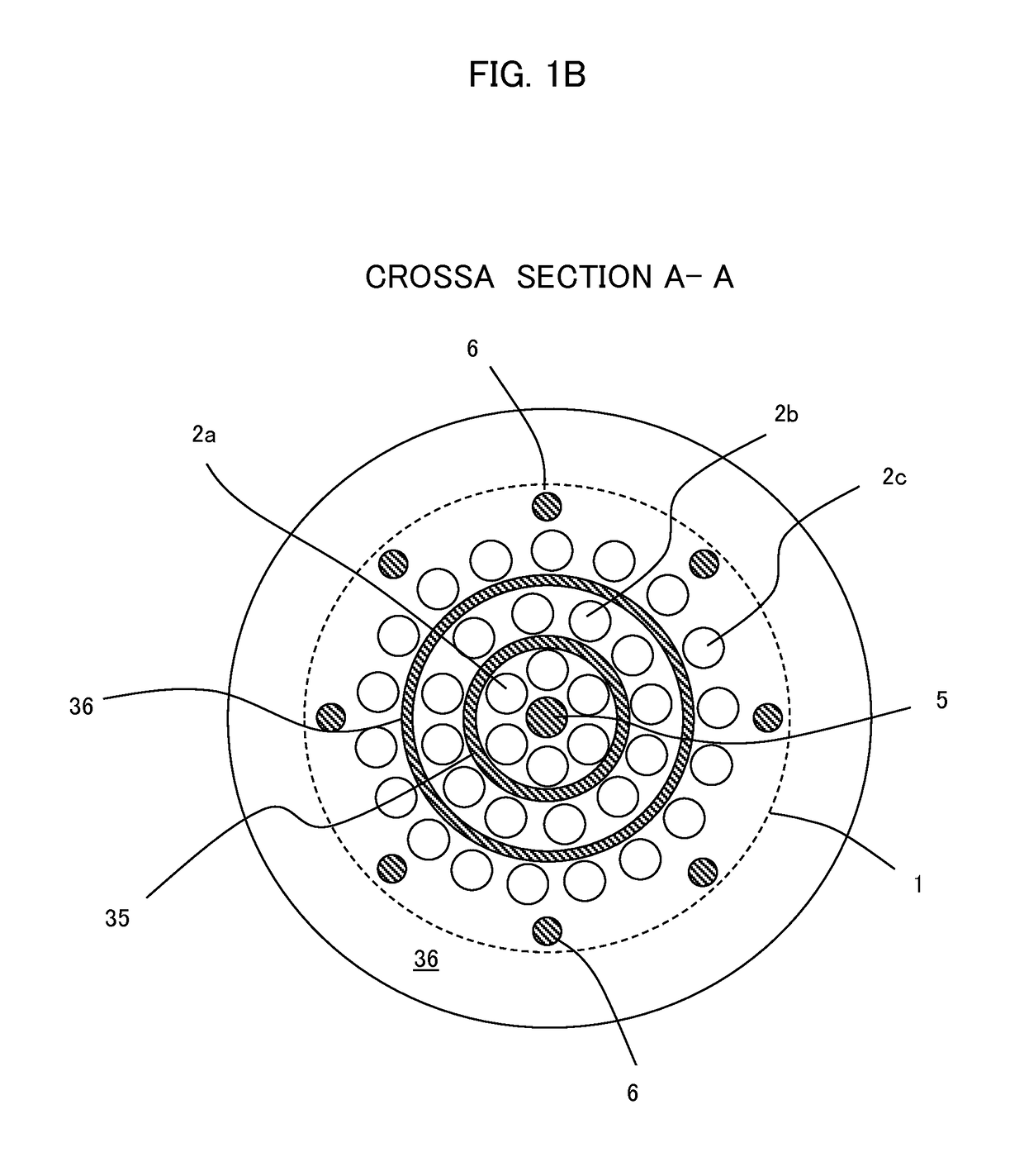
[0021]FIGS. 1A and 1B show construction of a burner section of a gas turbine combustor according to the present invention, FIG. 1A being a sectional view and FIG. 1B being an external view of cross section A-A in FIG. 1A, viewed in the direction of the arrows.
[0022]Referring to FIGS. 1A and 1B, the burner section of the gas turbine combustor is a cluster-type burner that includes a plurality of fuel nozzles 2 and a premixing plate 4 in which are formed a plurality of premixing passages 3 each positioned at a downstream side of one of the fuel nozzles 2. The plurality of fuel nozzles 2 are connected to an end face of a fuel nozzle header 1, and the premixing plate 4 is connected to the end face of a fuel nozzle header 1 via a central support rod 5 and a plurality of outer circumferential support rods 6. The plurality of fuel nozzles 2 include three arrays of fuel nozzles, namely an inner circumferential fuel nozzle 2a, a central fuel nozzle 2b, and an outer circumferential fuel nozzl...
fourth embodiment
[0043]the present invention is described below using FIGS. 6A and 6B. FIG. 6A is an external view equivalent to an upper half of the central support rod 5 and central guide vane 35 of the burner section in FIG. 1B. FIG. 6B is an external view of cross section B-B in FIG. 6A, viewed in the direction of the arrows.
[0044]The present embodiment is characterized by the fact that in addition to the annular flow sleeve 35, a protruding vane 63 for rectifying an axial flow of combustion air is disposed on an inner circumferential surface of the annular flow sleeve 35, near a downstream end of this annular flow sleeve. The protruding vane 63, as shown, is a triangular vane whose vertex as viewed in transverse section faces toward a central axis of the vane. Mounting the triangular vane 63 in plurality and spacing the plurality of triangular vanes 63 in a circumferential direction and in parallel with respect to the axial direction allows the axial flow of the combustion air to be rectified a...
PUM
 Abstract
Description
Claims
Application Information
 - R&D
- Intellectual Property
- Life Sciences
- Materials
- Tech Scout
- Unparalleled Data Quality
- Higher Quality Content
- 60% Fewer Hallucinations
Browse by: Latest US Patents, China's latest patents, Technical Efficacy Thesaurus, Application Domain, Technology Topic, Popular Technical Reports.
© 2025 PatSnap. All rights reserved.Legal|Privacy policy|Modern Slavery Act Transparency Statement|Sitemap|About US| Contact US: help@patsnap.com


