Method for downhole leak detection
a leak detection and downhole technology, applied in the field of downhole leak detection, can solve the problem that the current method of finding well anomalies is not sufficiently reliabl
- Summary
- Abstract
- Description
- Claims
- Application Information
AI Technical Summary
Problems solved by technology
Method used
Image
Examples
example 1
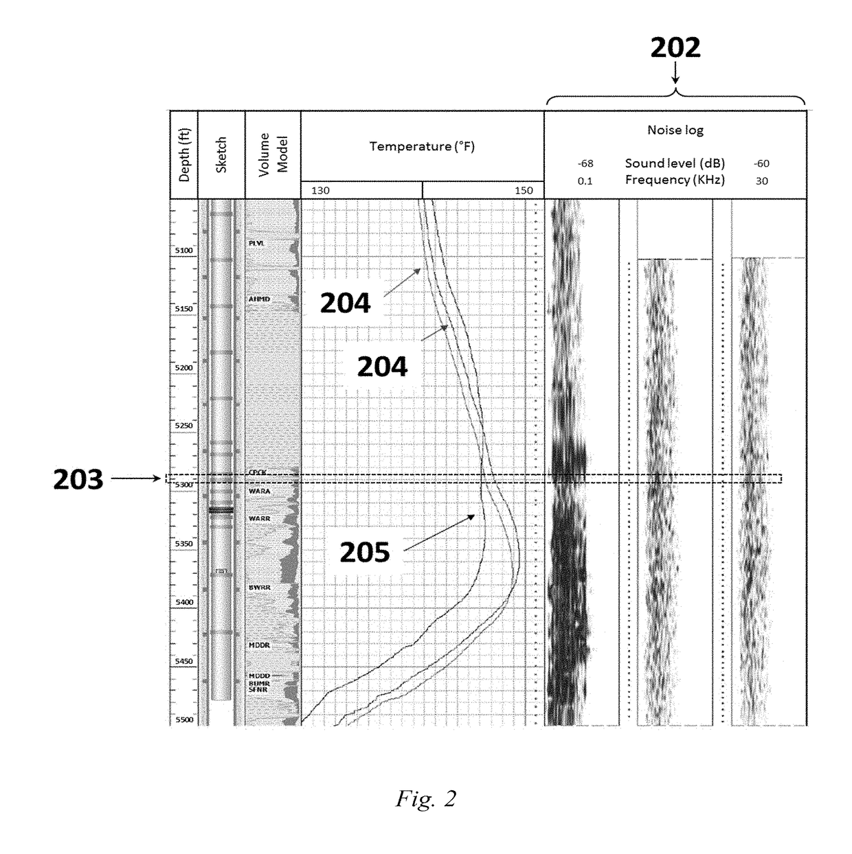
[0091]For downhole leak identification in oil, gas and water wells three aims were set. The first aim is to obtain different types of logs in order to find a new integrated approach. The second aim is to use the integrated method to detect downhole leaks by utilizing only rigless data based on full interpretation and evaluation of different logs in the field: temperature, noise, and thickness log. Finally, the last aim is to compare rigless approach results with conventional rig approach results for downhole leak detection.
example 2
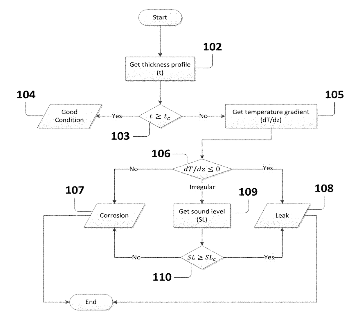
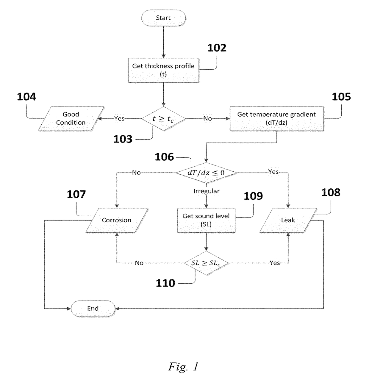
[0092]The developed integrated model is used to detect the downhole leak through analyzing only the numerical log data of corrosion, temperature and noise surveys. Based on the developed model, some instructions were implemented to allow the program decided that the completion in a specific depth is either leaked or only corroded or in a good condition. These rules were put based on these following surveys and in a specific order:
[0093]For corrosion survey, a corrosion factor was set such that, for a 4½″ tubing, 53% corrosion factor was implemented to the original tubing thickness which will indicate the presence of either corrosion or leak. If corrosion sigma (i.e. measured thickness) in a specific depth is less than 53% of the original tubing thickness, then the model highlights this location for more investigations by performing a temperature survey.
[0094]For a 7″ casing, 39% corrosion factor from the original thickness was implemented to the original casing thickness which will ...
example 3
[0098]The results of the developed model verify the conventional rig approach results. However, there is still a minor difference between the developed model and the conventional rig approach results. This difference may be due to accuracy of the results implying that what is predicted by the developed model is often more accurate than a manual prediction. The maximum noticed frequency in a well was 18 KHz and the minimum was zero. So, our reference noise frequency (i.e. the frequency threshold) is 9 KHz. In this case, if the frequency in a specific depth is greater than or equal to 9 KHz, this will confirm the presence of leak only if it is supported by the presence of damage from the thickness profile and the temperature log.
PUM
| Property | Measurement | Unit |
|---|---|---|
| inclination angle | aaaaa | aaaaa |
| inclination angle | aaaaa | aaaaa |
| inclination angle | aaaaa | aaaaa |
Abstract
Description
Claims
Application Information
 - R&D
- Intellectual Property
- Life Sciences
- Materials
- Tech Scout
- Unparalleled Data Quality
- Higher Quality Content
- 60% Fewer Hallucinations
Browse by: Latest US Patents, China's latest patents, Technical Efficacy Thesaurus, Application Domain, Technology Topic, Popular Technical Reports.
© 2025 PatSnap. All rights reserved.Legal|Privacy policy|Modern Slavery Act Transparency Statement|Sitemap|About US| Contact US: help@patsnap.com


