Al technical title is built by PatSnap Al team. It summarizes the technical point description of the patent document.
a fluid-conducting line and fluid-conducting technology, applied in the direction of sleeve/socket joint, pipe heating/cooling, mechanical equipment, etc., can solve the problem of certain degree of unreliability in terms of leakproofness, and achieve the effect of cost saving
Active Publication Date: 2018-10-30
EUGEN FORSCHNER
View PDF35 Cites 2 Cited by
Summary
Abstract
Description
Claims
Application Information
AI Technical Summary
This helps you quickly interpret patents by identifying the three key elements:
Problems solved by technology
Method used
Benefits of technology
[0009]Preferably in this context at least one spacer element is formed on the floor of at the bottom of each of the spacers of each of the annular spacers, which spacer element forms a stop, spaced apart from the bottom for the end of each of the lines. This arrangement ensures sealed enclosure and therefore, owing to the large adhesive surfaces which are made available at the end sides and the lateral side particular reliable securement of the lines with respect to the drilled hole which passes through, and a compact design is also made possible. As an alternative to a connection by means of adhesion, the device is preferably embodied in such a way that each of the fluid-conducting lines is secured in the annular space by means of friction welding, ultrasonic welding or laser welding. The advantage of a welding method for securing the lines is that such a method permits rapid and cost-effective manufacture of the device. The satisfactory positioning of the line ends before the welding is ensured by their arrangement in the annular spaces.
[0019]In one preferred embodiment, the housing has a recess for receiving a control circuit board. As a result of the integration of a control circuit board, an even more compact design for an individual heating power controller of the connected lines or line sections is made possible. Fewer individual elements are required for the manufacture, which provides a further cost saving.
Problems solved by technology
Furthermore, an additional detachable intermediate connection such as, for example, a sleeve is required as a result of which a certain degree of unreliability arises in terms of the leakproofness.
Method used
Image
Click on the blue label to locate the original text in one second.
Reading with bidirectional positioning of images and text.
Examples
Embodiment Construction
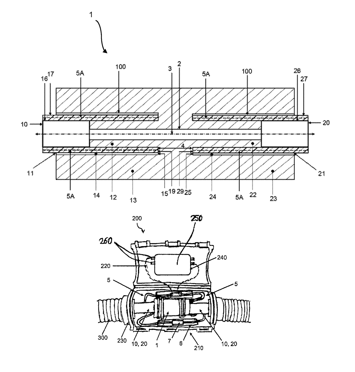
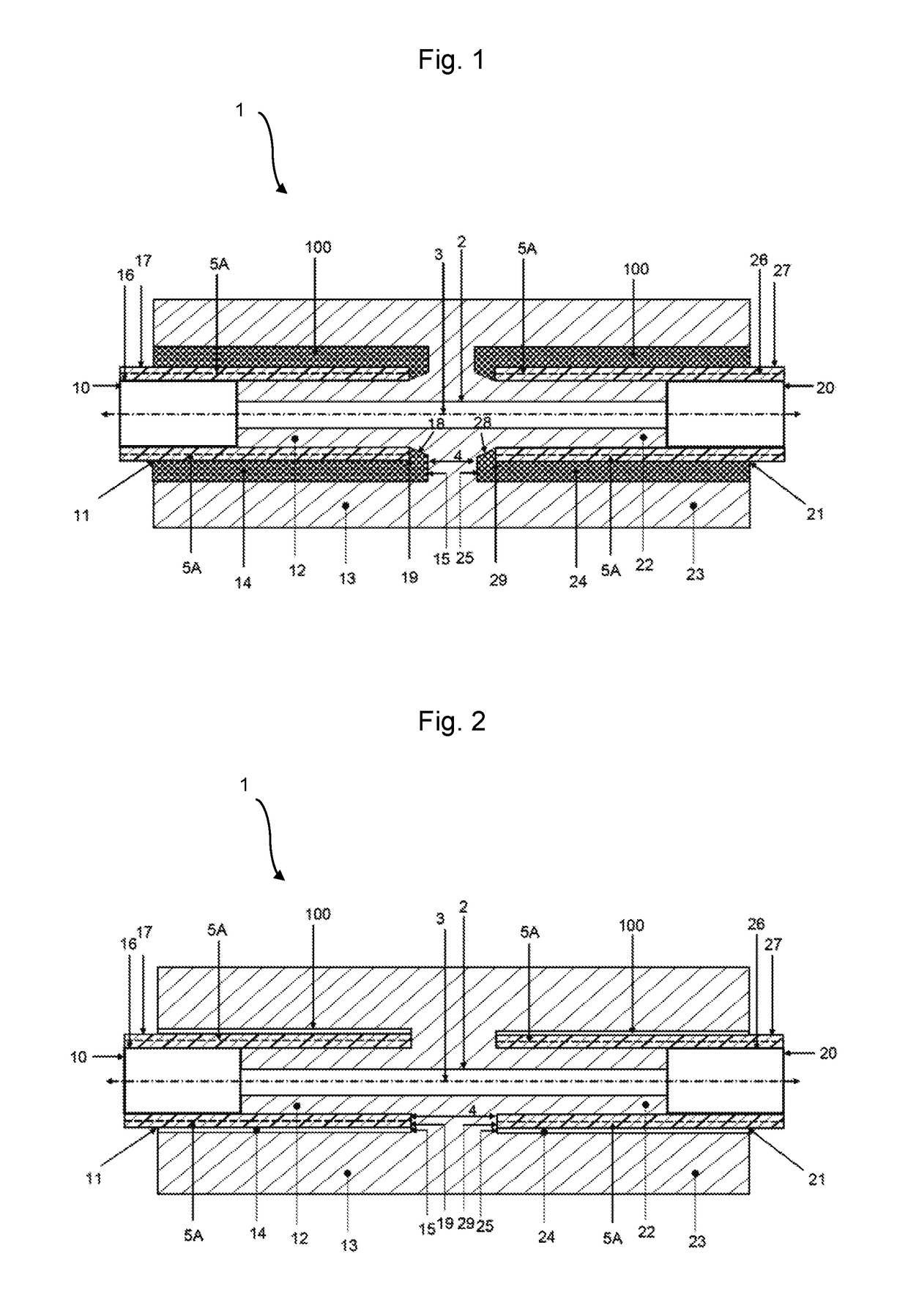
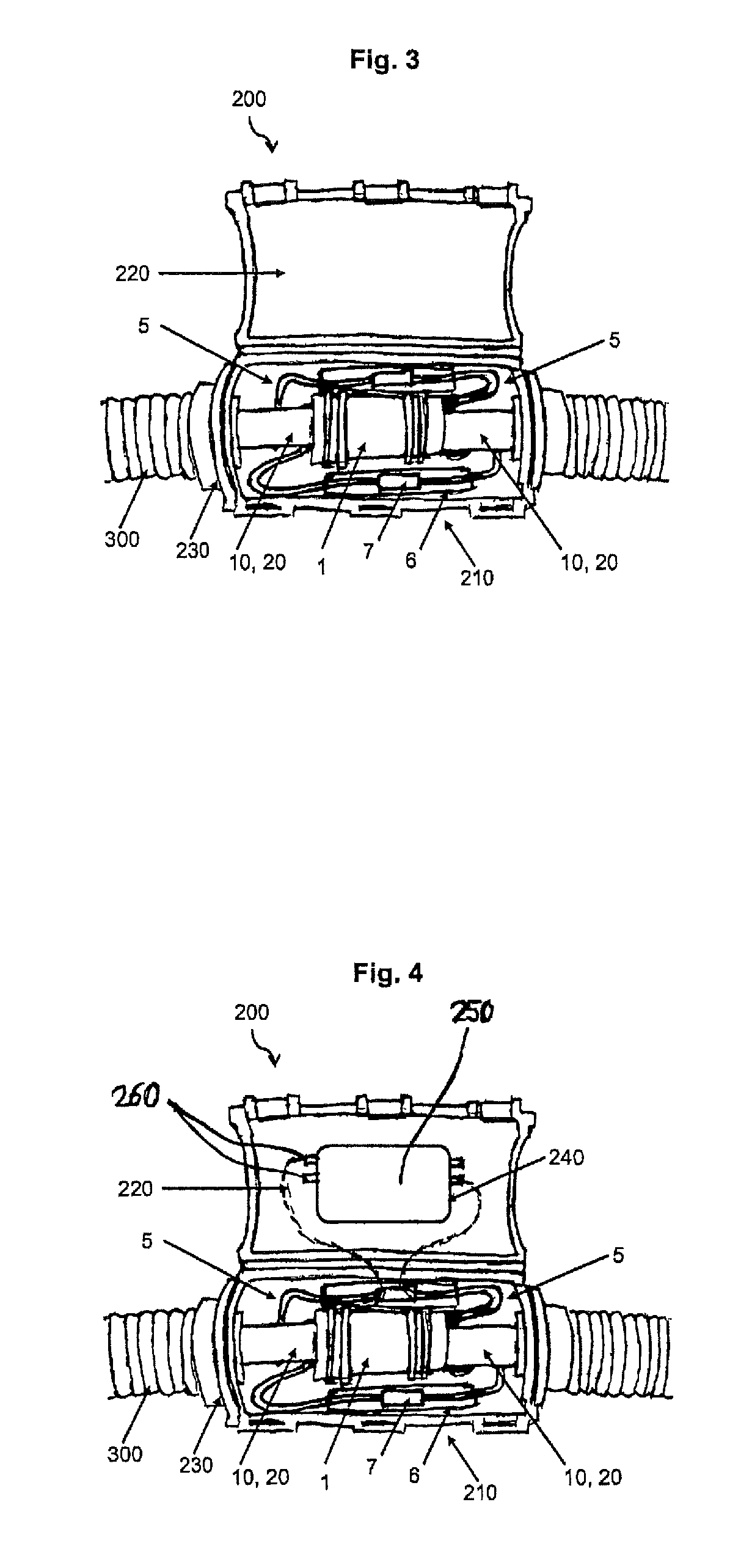
[0025]FIG. 1 is a schematic illustration of a first exemplary embodiment of a device 1 according to the invention. The device 1 is penetrated in the direction of its longitudinal axis by a continuous drilled hole 2, with the device 1 has an opening at it respective ends in the direction of the longitudinal axis 3. However, in contrast to the illustration in the figures, an angled device, in which the longitudinal axis within the device is bent or curved, and as a result experiences a change in angle of, for example, 90° C. is also possible.
[0026]A line receptacle (21) is provided at each of the ends of the device, each of which line receptacles 11, 21 can receive a fluid-conducting line 10, 20. The one line receptacle 11 ends within the device 1 at a predetermined distance 4 from the other line receptacle 21, with the result that, apart from the continuous drilled hole 2, there is no fluid connection between the line receptacles 11 and 21.
[0027]The line receptacles 11, 21 are embodi...
PUM
Property
Measurement
Unit
temperature
aaaaa
aaaaa
temperature
aaaaa
aaaaa
temperature
aaaaa
aaaaa
Abstract
The invention relates to a device (1) for connecting two fluid-channeling lines (10, 20), wherein the device has a through-bore (2) for advancing the fluid and two opposite line mounts (11, 21), which terminate at a predetermined distance (4) from one another within the device. Each of these line mounts (11, 21) is designed such that it is provided with a first part (12, 22), through which the through-bore (2) leads, and a second part (13, 23), which enclosed the first part (12, 22), an annular space (14, 24) therefore being formed between the first part (12, 22) and the second part (13, 23). Each of the two fluid-channeling lines, (10, 20) is arranged in one of the line mounts (11, 21) such that it has an inner cross section (16, 26) arranged, and fixed, with sealing action against the first part (12, 22) of the device and has an outer cross section (17, 27) arranged, and fixed, in the annular space (14, 24).
Description
FIELD OF THE INVENTION[0001]The invention relates to a device for connecting two fluid-conducting lines to one another.BACKGROUND OF THE INVENTION[0002]German utility model DE 1 732 279 U1 discloses a connection between two fluid-conducting lines, to be more precise a connecting element for connecting two housing hoses. The connecting element is embodied as a single-piece component through which a continuous drilled hole leads and which is provided at its outer side with a thread which is embodied in opposite directions, with the result that two garden hoses can easily be connected to one another by screwing onto the thread, and disconnected again from one another.[0003]In addition, European Patent EP 2 035 737 B1 discloses a sleeve for connecting two pipes which are each embodied with a connecting collar. The sleeve can be fitted here over the connecting collars of the pipes to be connected and can be fastened against unintentional removal by a locking device against unintentional ...
Claims
Application Information
Patent Timeline
Application Date:The date an application was filed.
Publication Date:The date a patent or application was officially published.
First Publication Date:The earliest publication date of a patent with the same application number.
Issue Date:Publication date of the patent grant document.
PCT Entry Date:The Entry date of PCT National Phase.
Estimated Expiry Date:The statutory expiry date of a patent right according to the Patent Law, and it is the longest term of protection that the patent right can achieve without the termination of the patent right due to other reasons(Term extension factor has been taken into account ).
Invalid Date:Actual expiry date is based on effective date or publication date of legal transaction data of invalid patent.