
LED light linear strip, mounting structure and clip assembly

a technology of led light strips and led light strips, which is applied in the direction of semiconductor devices for light sources, lighting and heating apparatus, and light support devices. it can solve the problems of limiting the length of led light strips that can run before they must be re-powered, unable to carry very much power, and becoming less desirabl

Active Publication Date: 2018-10-23
HOFFMAN JEREMY P
View PDF43 Cites 2 Cited by
  • Summary
  • Abstract
  • Description
  • Claims
  • Application Information

AI Technical Summary

Benefits of technology

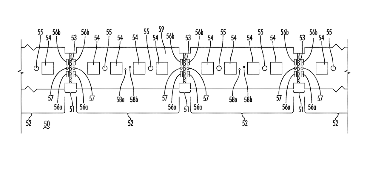
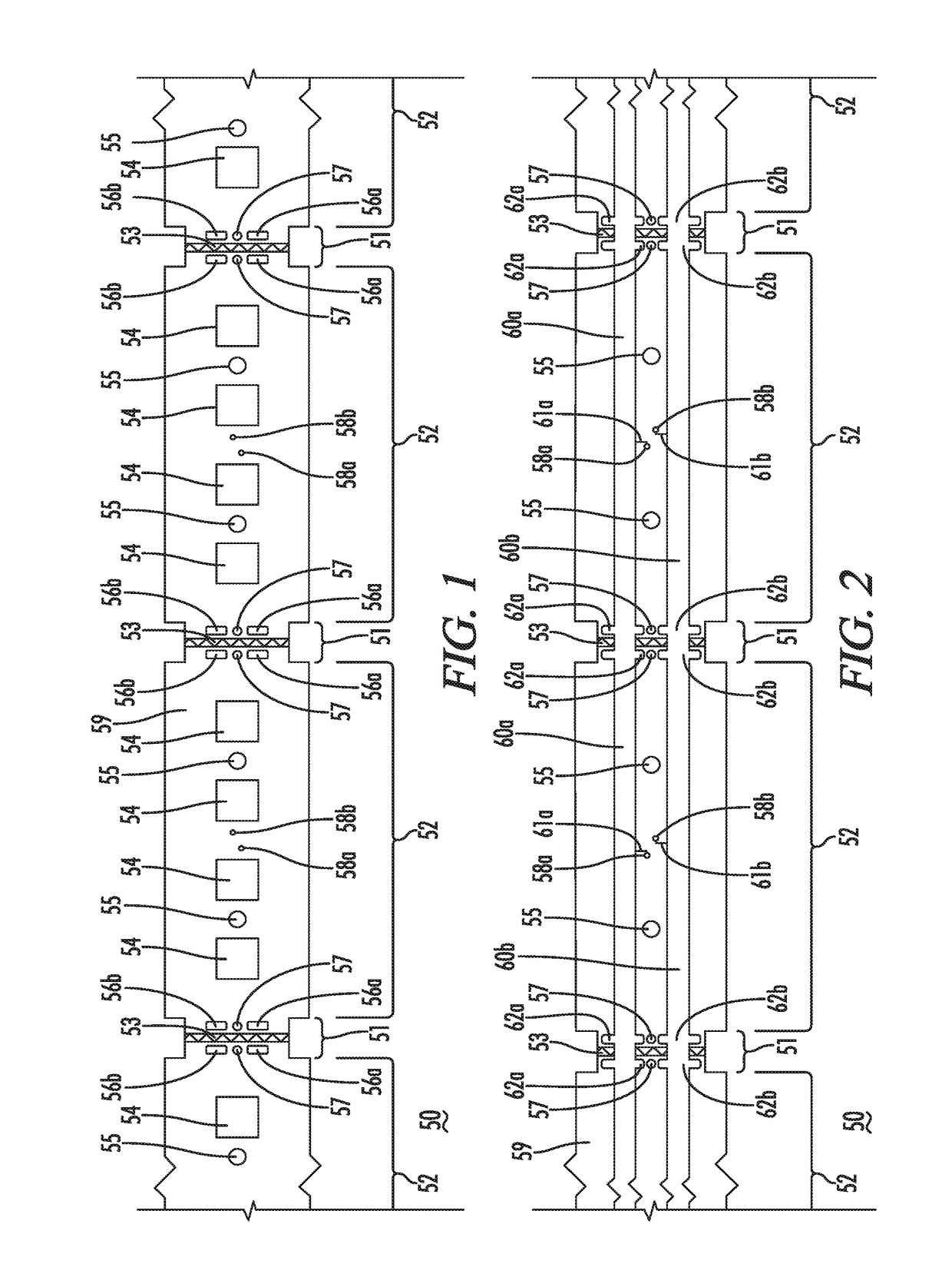
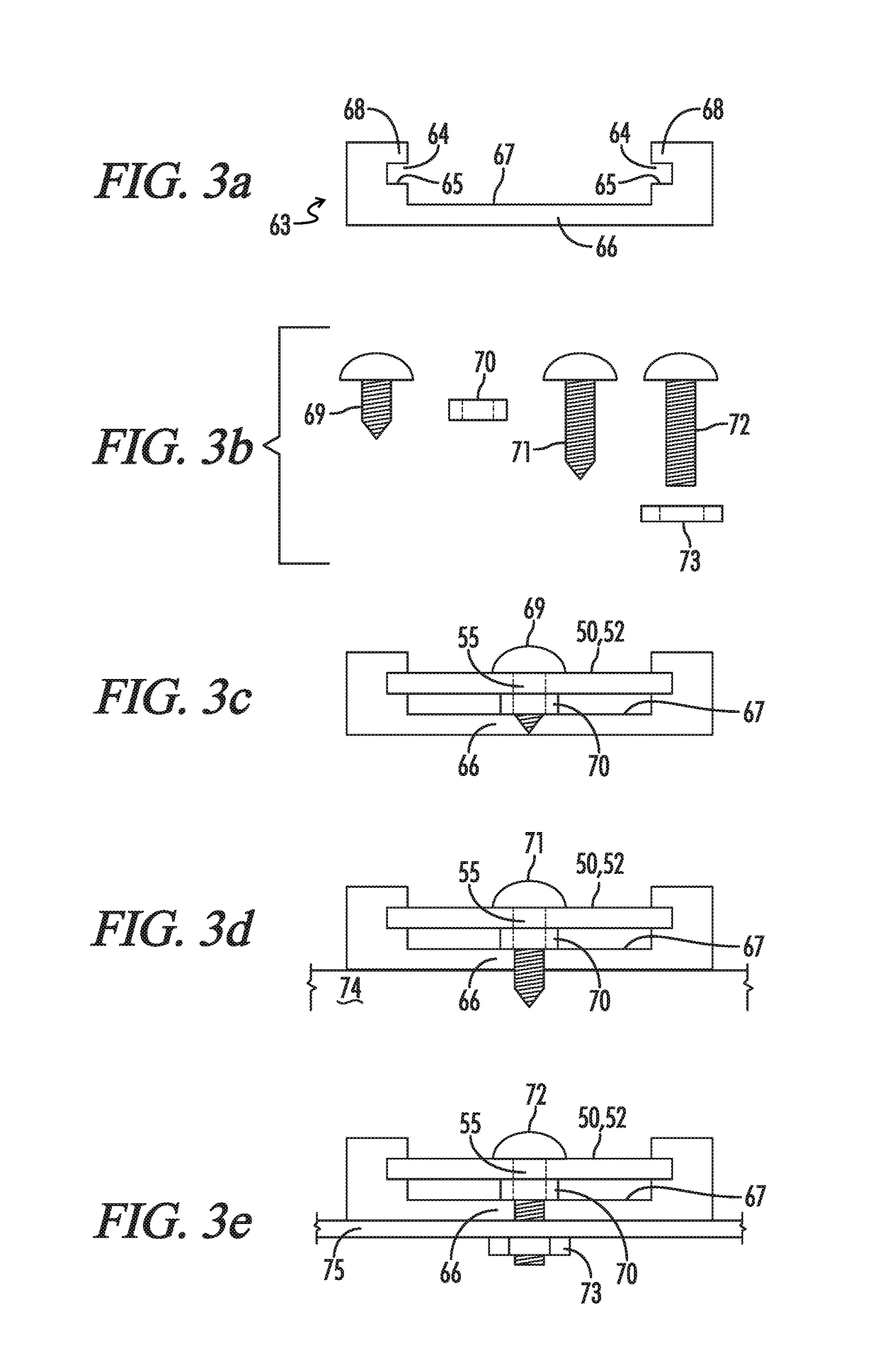
[0008]The mounting structure within which the LED light strip of the present invention is installed contains a floor that is spaced apart from the underside of the LED light strip when installed. The mounting structure also contains a pair of opposing slots into which the edges of the main light producing section of the LED light strip are inserted. The LED light strip has a structural core or support structure along its length that is strong and sturdy enough to provide a physically secure structure of some thickness, flexibility and elasticity such that it can be deformed, as by pinching, so that the edges of the wider main light producing section can be installed into the slots. The elasticity ensures that the LED light strip returns to its original shape after installation in the slots within the mounting structure sides. Primary installation is completed when a fastener is secured through the light producing section of the LED light strip and through a height maintenance structure placed in the mounting structure underneath the LED light strip, which height maintenance structure establishes and maintains the height of the center portion of the LED light strip, transverse to its length, while the slots in the mounting structure maintain the height of the edges of the main light producing section of the LED light strip of the present invention. When the LED light strip of the present invention is installed in the mounting structure, a resulting compartment is created underneath the entirety of the installed LED light strip excepting the edge portions of the main light producing sections which are inside the mounting structure slots along the length of its sides. The LED light strip of the present invention is always installed within the mounting structure such that the LED light producing elements are facing out of the mounting structure, so as to effectively provide light to a space, with the underside of the LED light strip facing into the resulting compartment. The outward facing side of the LED light strip may be referred to as the top of the LED light strip and, correspondingly, the side of the LED light strip facing the compartment inside the mounting structure may be referred to as the bottom of the LED light strip.
[0010]Moving the electrical power bus(es) underneath the LED light strip and within the compartment resulting from installation within the mounting structure provides several advantages. First, the cross sectional space available for the busses is increased, since they do not have to share space with the LED light producing elements and associated circuitry. This allows for larger conductors which allows for more power to be carried further, allowing longer runs of LED light strip from a higher power source. The compartment also provides some physical protection, and may allow for higher power levels to be deployed while the shock risk to individuals is minimized.
[0013]One of the benefits of this novel LED light strip, mounting structure and clip system is that the presence of a clip does not at all change the installed position of the LED light strip along the length of the mounting structure. The installation fasteners which secure the LED light producing section of the LED light strip will use the same holes in the mounting structure before and after clip installation. Operations such as replacing one failed section of LED light strip can be undertaken without changing the original installation. Configuration changes of control signal lengths and power bus lengths can occur without altering an original installation. The removable portion of the clip section also allows for a fail-safe to ensure that a power bus break is executed correctly by including a piece of plastic or other insulating material that rises vertically from the lower clip half and into the space between the two sides of a clip section where the removable portion of the clip section would otherwise be. This fail-safe barrier both provides an electrically insulating barrier between two power bus segments and prevents the clip sections from being installed unless the removable section is, in fact, removed.
[0014]An additional benefit is the ability to provide plug-and-play access to power for other external devices from the bus(es) underneath the LED light strip. Such a clip assembly would contain electrical contacts for the power bus underneath the LED light strip, the removable portion of the clip section would not need to be removed, and there would be no need for control signal contacts in the upper clip half. There would also be external wires which are connected to the lower clip half electrical contacts using methods known in the art and can be installed on any LED light strip clip section that does not already contain a clip. As long as there is available wattage on that power bus, this power can be extracted without changing any other aspects of the original installation.
[0015]One particular aspect of the clip and LED light strip system is the ability to leverage the flexibility and elasticity of the LED light strip structure to provide a continuing force ensuring continued stable electrical contact within a clip, especially at the power busses where more contact transmission is necessary. The clip halves establish electrical connection by matching contact areas on the LED light strip with aligned contact areas within the respective clip halves. The clip halves are secured against each other and over the clip section of the LED light strip, either by a snap fit or by common nut and bolt type assembly, or other mechanically fastening methods known in the art. By designing the electrical contact portions of the clip halves such that they press into their respective contact on the LED light strip in such a manner that the contact on the LED light strip is pressed into the flexible structure of the LED light strip, the elasticity of the structure provides a countering force that presses the two contacts together. Therefore, an advantage of this invention is that the flexibility and elasticity of the structure of the LED light strip, which is required for installation, also provides flexibility for the structure to deform as the clip halves are joined together and their respective contacts are forced into the LED light strip which provides a force due to the structure attempting to return to its original form. It is this counter force that ensures electrical contact within the clip halves.

Problems solved by technology

A drawback to this approach is that the conductors must also be narrow, and consequently they cannot carry very much power.
This limits the length an LED light strip can run before it must be re-powered, often to 10 meters or less.
This is most often due to voltage drop, or the resistive losses associated with running too much power through too small conductors.
Some LED light strip systems still use a direct solder connection method, but those are less desirable and becoming less common.
The need to create space between newly separated LED light strip sections for clip installation is particularly problematic when replacing a broken or defective section of LED light strip, since a replacement section for the defective section must have a clip to connect the section to the existing installation at each end of the replacement section, requiring significant modification to the original installation.
Another challenge of LED light strips is that their structure is not very durable or strong.
Such an installation does not provide a high degree of mechanical security to an installation, and makes service, repair and reconfiguration more difficult.

Method used


Image

  • LED light linear strip, mounting structure and clip assembly
  • LED light linear strip, mounting structure and clip assembly
  • LED light linear strip, mounting structure and clip assembly

Examples


Embodiment Construction

[0033]The following detailed description is of the best mode or modes of the invention presently contemplated. Such description is not intended to be understood in a limiting sense, but to be an example of the invention presented solely for illustration thereof, and by reference to which in connection with the following description and the accompanying drawings one skilled in the art may be advised of the advantages and construction of the invention. Reference will now be made in detail to a preferred implementation of the present invention as illustrated in the accompanying drawings. Wherever possible, the same reference numbers will be used throughout the drawings to refer to the same or like parts.

[0034]Before the present invention is disclosed and described, it is to be understood that the terminology used herein is for the purpose of describing particular embodiments only and is not intended to be limiting. The terms “a” or “an”, as used herein, are defined as one or more than ...


PUM


Abstract

A system and method comprised of an LED light strip whose electrically insulating core structure is somewhat flexible and elastic and whose alternating light producing sections and narrower clip sections have a top side containing LED elements and control signals and an underside containing a high capacity voltage bus, and a three sided mounting structure where an installed LED light strip is the fourth side with LED elements facing out and the voltage bus protected inside, and a clip system of two halves which affix to each other around a narrower clip section with a lower half connecting electrically to the voltage bus under the narrower clip section and installing in one side of the mounting structure and an upper half connecting electrically to control signals on the top half of the narrower clip section and installing in the other side of the mounting structure.

Description

FIELD OF THE INVENTION[0001]The present invention relates to lighting devices, and more particularly to LED lighting devices including a mounting structure and clip assembly for factory or field assembled luminaires.BACKGROUND OF THE INVENTION[0002]LED based lighting has increasingly become an attractive mode of lighting used for many purposes. One of the advantages of LED lighting is the ability to create long linear runs of individual LED elements which are wired into LED light strips. LED light strips can take many forms, but most have a narrow width and a continuous length which can be divided into smaller sections whose lengths vary, but are usually under six inches in length. These LED light strips are flat and produce light with a wide beam angle and are well suited to a variety of applications. Usually these LED light strips are composed of a flexible printed circuit which is printed on a thin flexible substrate where that substrate is not much wider than the LED elements th...

Claims


Application Information

Patent Timeline
Patent Type & Authority Patents(United States)
IPC IPC(8): F21V19/00F21S4/22H05B33/08F21V21/088H05B37/02F21Y103/10F21Y115/10H05B44/00
CPCF21S4/22F21V19/003F21V21/088H05B37/0254H05B33/0845F21Y2115/10F21Y2103/10F21S4/24F21V23/06F21V19/0055F21V21/005F21S4/28F21S2/00Y02B20/30H05B45/30H05B45/10H05B47/18H05B45/00
Inventor HOFFMAN, JEREMY P.
Owner HOFFMAN JEREMY P
Learn More