
Process for simultaneous production of benzene lean gasoline and high purity benzene from cracked gasoline fraction

a technology of benzene lean gasoline and cracking, which is applied in the direction of hydrocarbon oil treatment products, vacuum distillation separation, separation processes, etc., can solve the problems of economic and reliable benzene recovery process that is difficult to develop, has not been practiced, and has no technology in operation worldwide, so as to improve product yield and purity, and reduce operating and equipment costs

Active Publication Date: 2018-10-23
COUNCIL OF SCI & IND RES
View PDF2 Cites 0 Cited by
  • Summary
  • Abstract
  • Description
  • Claims
  • Application Information

AI Technical Summary

Benefits of technology

The present invention provides a process for making high purity benzene from cracked gasoline that improves product yield and purity while reducing operating and equipment costs. The process is simple and energy-efficient, with no need for expensive purification equipment. This makes the overall plant less expensive and easier to install.

Problems solved by technology

The relationship of feed properties and reaction process conditions to the production of various compounds in a FCC unit is complex and thus does not present a straight forward solution for benzene control.
Due to the complex nature of this feedstock, an economic and reliable benzene recovery process is difficult to develop and has not been practiced in the industry so far.
There are no technologies in operation worldwide which serve the dual purpose of producing benzene lean streams from a petroleum feedstock (like the ones mentioned above), by simultaneously recovering high purity benzene.

Method used


Image

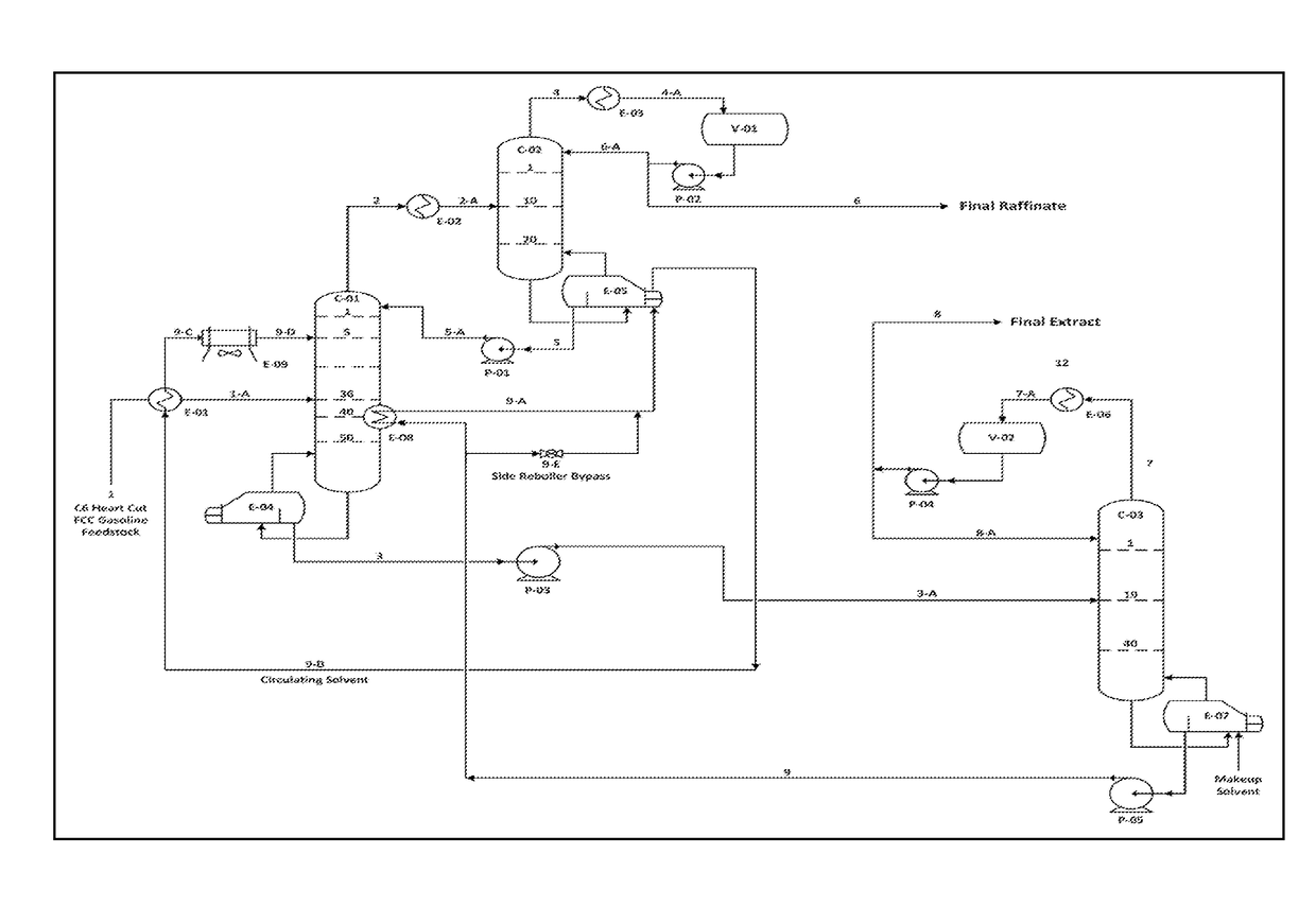
  • Process for simultaneous production of benzene lean gasoline and high purity benzene from cracked gasoline fraction
  • Process for simultaneous production of benzene lean gasoline and high purity benzene from cracked gasoline fraction
  • Process for simultaneous production of benzene lean gasoline and high purity benzene from cracked gasoline fraction

Examples


example 1

Tuning Component Interaction Parameters

[0081]Experimental ED column run with NMP+Water (97.8:2.2) wt. % described in Table 4 of U.S. Pat. No. 8,722,952 B2 has been used for fine tuning component interaction parameters which were used in the simulation cases described in Examples 2, 3, 4, 5 and 6 of the current invention.

[0082]A simple extractive distillation model similar to the one used for experimentation in the lab was developed in a commercial process simulator. Typical column operating parameters in the simulation model like (number of stages, reflux ratios, hydrocarbon feed, solvent, column top and bottom product flow rates, etc) were kept same as that maintained during the lab run.

[0083]The component interaction parameters were rigorously fine tuned so that the product profiles (flow rates and compositions) of the simulation model matched the corresponding values obtained during the experimental run.

[0084]The following column operating parameters have been reported in Table 4...

example 2

n Results of the Base Case

[0095]In this example, simulation results of the process illustrated in FIG. 3 of the previous patent (U.S. Pat. No. 8,722,952 B2) are presented.

[0096]Referring to FIG. 3 of U.S. Pat. No. 8,722,952 B2; ED Run with NMP and Water (97.8:2.2) wt. % (With side reboiler at Stage 55 in Col. 1)[0097]Main ED Column operating pressure (Top pressure—0.031 Kg / cm2g)[0098]Solvent Recovery Column operating pressure (Top pressure—0.207 Kg / cm2g)[0099]Hydrocarbon Feed: Benzene concentrated unprocessed catalytically cracked gasoline fraction (boiling in the range 48° C.-92° C.) as described in Table 1 with a flow rate of 70 tph[0100]Solvent System: Mixture of NMP and Water (97.8:2.2) wt. %[0101]Solvent Entry Temperature in Main ED Column: 60° C.[0102]Hydrocarbon Feed to Main ED column vapor fraction: 0.8 at 0.288 kg / cm2g[0103]Process Flow Scheme as in FIG. 3 of U.S. Pat. No. 8,722,952 B2[0104]Solvent System to Feed Wt. Ratio in main ED column—4.0:1.0[0105]ED Column / Solvent Re...

example 3

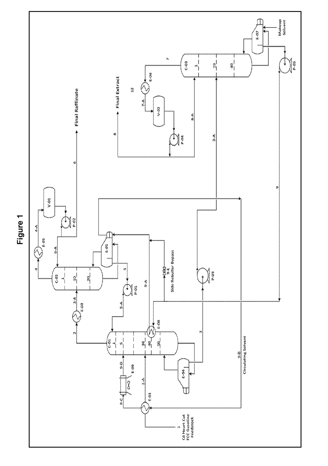
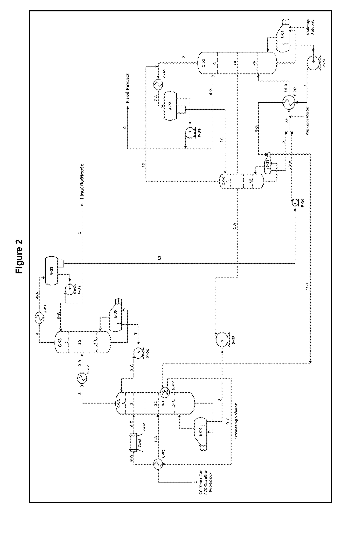
[0112]ED Run with NMP and Water (97.8:2.2) wt. % (With side reboiler at Stage 40 in Col. 1)[0113]ED Column (Col.1) operating pressure (0.517 Kg / cm2g)[0114]Feed: Benzene concentrated unprocessed catalytically cracked gasoline fraction (boiling in the range 48° C.-91.8° C.) as described in Table 1 (90% vaporization at 0.65 kg / cm2g)[0115]Solvent System: Mixture of NMP and Water (97.8:2.2) wt. %[0116]Solvent Entry Temperature in Col. 1: 90° C.[0117]Process Flow Scheme as in FIG. 2[0118]Solvent System to Feed Wt. Ratio—4.0: 1.0[0119]ED Column / Solvent Recovery Column Stage Efficiency—0.50

[0120]Individual Column operating parameters are provided in Table 4 as follows:

[0121]

TABLE 4-AColumn Operating Parameters for Example 3 (Refer FIG. 2)EDC-1EDC-2SRCEWSParametersUOM(C-01)(C-02)(C-03)(C-04)Total Number of StagesActual50204010Stage Efficiency assumed0.50.50.50.5Main Feed Stage Location3610201Column Top PressureKg / cm2g0.50.10.2580.5Reboiler Temperature° C.180.84100.58182.50113.38Reboiler Duty...


PUM

PropertyMeasurementUnit
weight ratioaaaaaaaaaa
temperatureaaaaaaaaaa

Abstract

Disclosed is a process for simultaneous production of benzene lean gasoline and recovery of high purity aromatics from narrow boiling light cracked gasoline fractions. The present invention provides a vacuum based two stage extractive distillation process, with pure NMP, for production of benzene lean gasoline (benzene content less than 0.4 Weight %) by recovery of high purity aromatics (purity more than 99 Weight %) from cracked gasoline fractions (boiling in the range of 40-90° C.) comprising benzene in the range of 10-30 weight % and close-boiling non-aromatic hydrocarbons like paraffins, iso-paraffins, olefins, di-olefins (including conjugated di-olefins), and naphthenes in the range of 70-90 weight % along with impurities containing but not limited to oxygenates, metals, chlorides, sulphur compounds, nitrogen compounds and organic peroxides.The present invention provides an improved extractive distillation process for simultaneous production of benzene lean gasoline and benzene rich product from cracked gasoline fraction, with higher recovery of better quality products along with lower utility requirements and investment costs.

Description

CROSS-REFERENCE TO RELATED APPLICATION[0001]This application claims priority to India patent application no. 0871 / DEL / 2015, dated Mar. 30, 2015, the disclosure of which is hereby incorporated by reference in its entirety.FIELD OF THE INVENTION[0002]The present invention relates to a process for simultaneous production of benzene lean gasoline and recovery of high purity aromatics from narrow boiling light cracked gasoline fractions.[0003]Particularly, the present invention relates to a vacuum based two stage extractive distillation process, with pure NMP, for production of benzene lean gasoline (benzene content less than 0.4 Weight %) by recovery of high purity aromatics (purity more than 99 Weight %) from cracked gasoline fractions (boiling in the range of 40-90° C.) comprising benzene in the range of 10-30 weight % and close-boiling non-aromatic hydrocarbons like paraffins, iso-paraffins, olefins, di-olefins (including conjugated di-olefins), and naphthenes in the range of 70-90 w...

Claims


Application Information

Patent Timeline
Patent Type & Authority Patents(United States)
IPC IPC(8): B01D3/10C10G21/28C07C7/08B01D3/40C10G53/06C10G55/06C10G21/20B01D3/00
CPCB01D3/40B01D3/007B01D3/10C07C7/08C10G21/28C10G53/06C10G55/06C10G21/20C10G2400/30C10G2400/02
Inventor GARG, MADHUKAR ONKARNATHGHOSH, PRASENJITKUMAR, SUNILNANOTI, SHRIKANT MADHUSUDANNAUTIYAL, BHAGAT RAM
Owner COUNCIL OF SCI & IND RES
Learn More