
Headset with magnetic frictional coupler

a frictional coupler and headset technology, applied in the field of frictional couplers, can solve the problems of variable adjustment performance, affecting the life of the product, and affecting the quality of the product, and achieve the effect of convenient manufacturing

Active Publication Date: 2018-10-16
HEWLETT PACKARD DEV CO LP
View PDF6 Cites 4 Cited by
  • Summary
  • Abstract
  • Description
  • Claims
  • Application Information

AI Technical Summary

Benefits of technology

[0006]A headset including a magnetic frictional coupler is described that includes magnetic elements arranged to establish a magnetic flux that varies according to relative positions of elements of the frictional coupler. Because the magnetic elements can comprise magnets that do not change in magnetic force over time, problems arising as prior art frictional couplers wear out can be reduced or eliminated. Also, the magnetic frictional couplers for headsets described herein can be small, can operate silently and can be easily manufactured.

Problems solved by technology

When headset frictional couplers are designed using metal, plastics and / or elastomers, the frictional force tends to change as the materials wear out and creep, over the life of the product.
Also, these types of materials present manufacturing and production difficulties, so they are made with tolerance that leads to variation in adjustment performance even when new.

Method used


Image

  • Headset with magnetic frictional coupler
  • Headset with magnetic frictional coupler
  • Headset with magnetic frictional coupler

Examples


Embodiment Construction

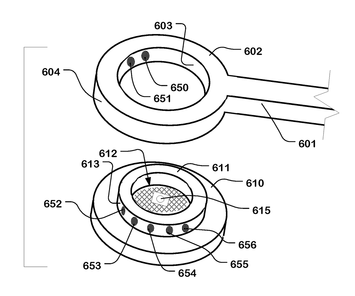
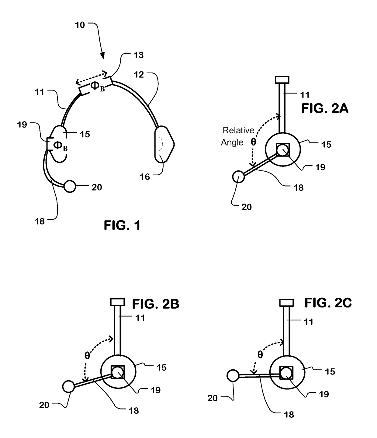
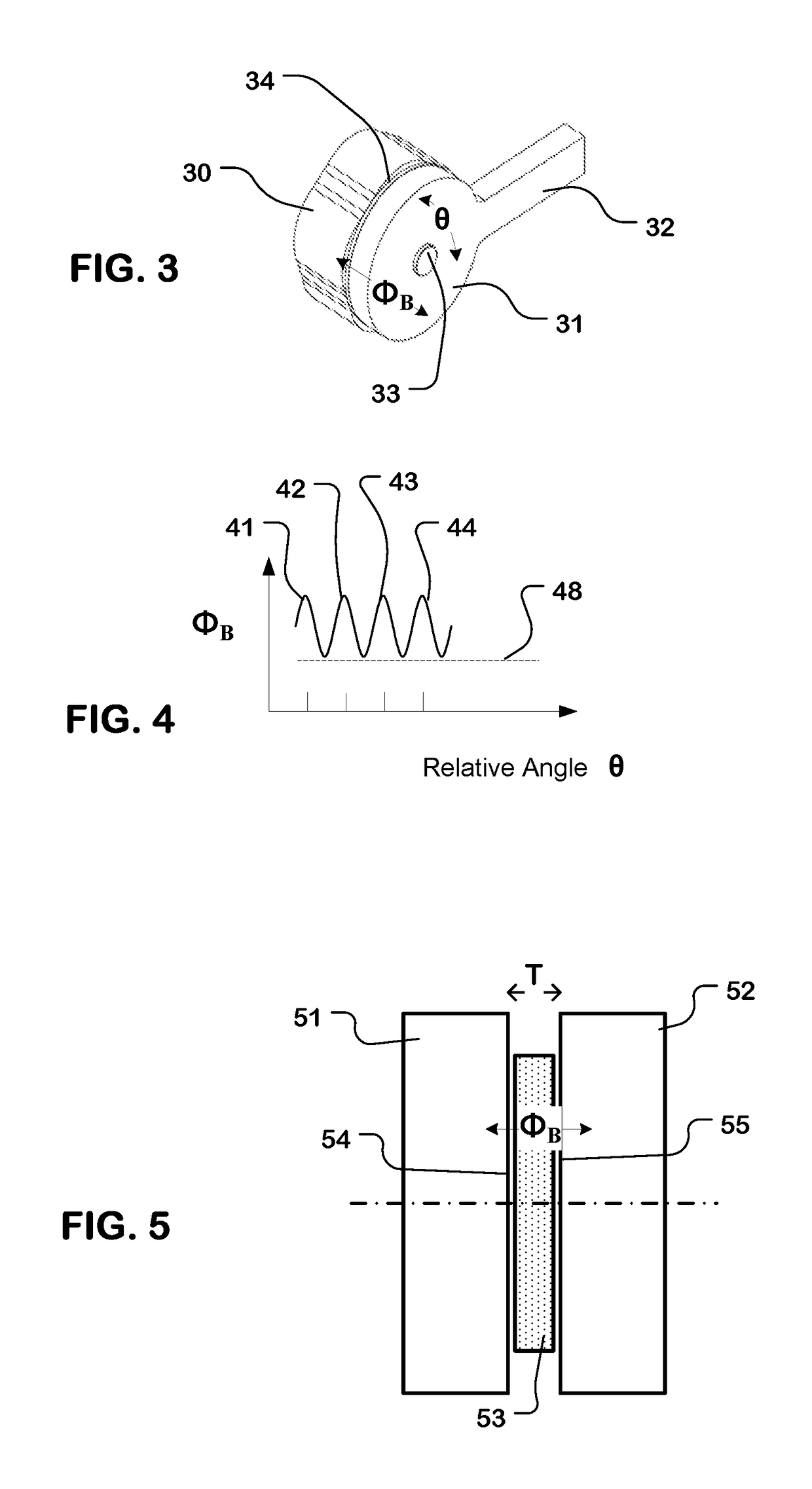
[0034]A detailed description of embodiments of the technology described herein is provided with reference to the FIGS. 1-21.

[0035]FIG. 1 is a simplified illustration of a headset 10 having a headband comprising a first member 11 and a second member 12 which are connected at their proximal ends by a magnetic frictional coupler 13 for translational adjustment. Speaker housings 15 and 16 are disposed on the distal ends of the members 11 and 12, respectively. The headset 10 also has a microphone boom 18 connected at its proximal end to a magnetic frictional coupler 19 connected to the speaker housing 15 or first headband member 11, for rotational adjustment. A microphone 20 is disposed on the distal end of the microphone boom 18.

[0036]The magnetic frictional coupler 13 for headband length adjustment and the magnetic frictional coupler 19 for the microphone boom angle adjustment include means for establishing a magnetic flux (measured for example in Webers W) which is a function of relat...


PUM


Abstract

A headset is described that utilizes magnetic frictional couplers. A coupler includes a first member having a first engagement surface and a second member having a second engagement surface disposed for relative positioning of the first and second members along a line of adjustment. One or more magnetic elements are arranged on the first and second members to establish a magnetic flux between the first engagement surface and the second engagement surface, and thereby establishing a frictional force tending to hold the relative positions of the first and second members. The magnetic flux varies as a function of relative position of the first and second members along the line of adjustment, and has peaks at a plurality of detent positions along the line of adjustment.

Description

BACKGROUND OF THE INVENTIONField of the Invention[0001]The present invention relates to frictional couplers for headsets with a rotating boom for positioning a microphone or other component, and / or an adjustable headband allowing for adjusting the fit of the headset.Description of Related Art[0002]Headsets are used in a variety of environments. For example, headsets are used in call centers so that the telephone operators can conduct conversations with their hands free. Many types of headsets include a rotating boom for positioning a microphone or other component to be used by the person wearing the headset. Also, many types of headsets have adjustable headbands which permit the user to adjust the length of the headband to improve the fit.[0003]For positioning booms and adjusting headbands, some types of headsets rely on frictional couplers. Some frictional couplers have positions that are controlled by plastic-on-plastic friction with or without detents. In some examples, detents c...

Claims


Application Information

Patent Timeline
Patent Type & Authority Patents(United States)
IPC IPC(8): H04R1/10H04M1/05
CPCH04R1/1066H04R1/1041H04R1/1008H04M1/05H04R1/105H04M1/6058A44D2203/00H01F7/0242H01F7/0263
Inventor MEYBERG, JACOB TLEE, BARRY JKELLEY, JOHN
Owner HEWLETT PACKARD DEV CO LP
Learn More