Hydraulic control arrangement for an automatic transmission

Active Publication Date: 2018-10-16
ZF FRIEDRICHSHAFEN AG
View PDF7 Cites 3 Cited by
  • Summary
  • Abstract
  • Description
  • Claims
  • Application Information

AI Technical Summary

Benefits of technology

The patent text describes a seat valve that has tight sealing and a simple design, compared to a slide valve that has gap leakage due to its design. The hydraulic control device also integrates a check valve in the switching component, which saves installation space.

Problems solved by technology

The disadvantage here is that the residual pressure in the clutch is gradually eliminated through the gap leakage caused by its design, and that the clutch can thus be drained, since the clutch valve is designed as a piston slide valve.

Method used


Image

  • Hydraulic control arrangement for an automatic transmission
  • Hydraulic control arrangement for an automatic transmission
  • Hydraulic control arrangement for an automatic transmission

Examples


Embodiment Construction

[0029]Reference will now be made to embodiments of the invention, one or more examples of which are shown in the drawings. Each embodiment is provided by way of explanation of the invention, and not as a limitation of the invention. For example features illustrated or described as part of one embodiment can be combined with another embodiment to yield still another embodiment. It is intended that the present invention include these and other modifications and variations to the embodiments described herein.

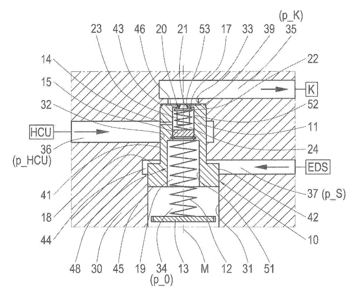
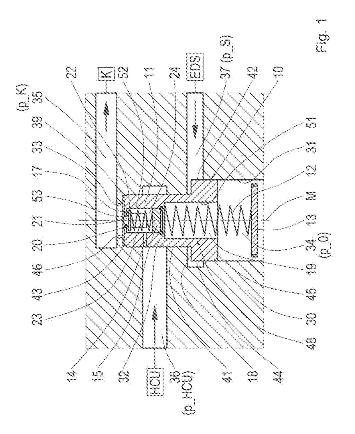
[0030]FIG. 1 shows a schematic view of the hydraulic control device in accordance with the invention with a switching valve 10 and a check valve 20 in the first switching position of the switching valve 10. The switching valve 10 comprises a switching component formed as a seat piston 11, whereas the seat piston 11 features a first cylindrical piston section 41 and a second cylindrical piston section 42. Thereby, the diameter of the first piston section 41 is smaller than that of t...


PUM


Abstract

A hydraulic control device for an automatic transmission including a valve device. The valve device comprising a switching valve, featuring a switching component and a check valve. The switching valve is formed in a housing and is hydraulically connected to a first pressure adjusting device and a second pressure adjusting device along with a shift element for transferring a certain torque. The switching valve is formed as a directional seat valve.

Description

FIELD OF THE INVENTION[0001]The invention relates to a hydraulic control device for an automatic transmission in a vehicle.BACKGROUND OF THE INVENTION[0002]For the presentation of various transmission ratio stages, automatic transmissions feature hydraulic shift elements, which are actuated by means of pressurization; that is, they are brought into an operating state in which a certain torque is transferable through the shift elements. For this purpose, a cylindrical space is to be filled with an operating medium, and subsequently a clutch piston is subjected to a certain pressure of the operating medium. The volume flow or pressure required for filling or pressurization is generated by a pump, which is driven by a drive unit of the automatic transmission. The amount of pressure is adjusted by a pressure adjusting device, whereas different pressure circuits may be present in the hydraulic system of a transmission. When the drive unit is at a standstill, the generation of pressure co...

Claims


Application Information

Patent Timeline
IPC IPC(8): F16H61/02F16H61/06F16K15/18F16K17/04F16K31/122F04C14/26F16D48/02
CPCF16H61/0276F04C14/26F04C14/265F16H61/0283F16H61/068F16K15/183F16K17/048F16K31/1221F16K15/18F16H2061/062F16D2048/0221F16H2061/0279F16K15/1823
Inventor SCHIELE, PETERGETHOFER, FRANK
Owner ZF FRIEDRICHSHAFEN AG
Why Eureka
Try Eureka